Noritz NCC199CDV Installation Manual
Commercial water heating system
Hide thumbs
Also See for NCC199CDV:
- Owner's manual (36 pages) ,
- Installation manual (59 pages) ,
- Instructional manual (23 pages)

Related Manuals for Noritz NCC199CDV


Summary of Contents for Noritz NCC199CDV
- Page 1 NCC199CDV Commercial Water Heating System (CR60) Installation Manual Additional information can be obtained from the appliance manual. Floor Standing Rack (CDV Units) 6 Water Heaters CR60-IM.v0429.4...
-
Page 2: Table Of Contents
Table of Contents Description....................................3 Before Installation .................................. 4 Venting the CR60 Commercial Rack System ........................10 Clearances ..................................... 21 Commercial Water Heating System Parts Number & Main Components ................26 CR60-WH-2 Specifications ..............................28 2 Unit Drawing Illustration / Dimensions ..........................29 CR60-WH-3 Specifications .............................. -
Page 3: Description
Description The Noritz Commercial Water Heating System (CR60) is a pre-fabricated racking solution that can be used in flat rooftop, mechanical room, or outdoor applications. For the wall mounted configurations, Commercial Water Heating Systems are available in 2 or 3 Noritz tankless water heater configurations. The floor standing Commercial Water Heating Systems are available with 4 , 5 or 6 unit Noritz tankless water heater configurations. -
Page 4: Before Installation
Before Installation • A licensed professional must install the Commercial Water Heating System (CR60) • Installer should have skills such as connecting gas line, water line, electricity, and knowledge of applicable national state and local codes. • Stop if you lack the skills above. Contact a licensed professional. CR60-IM.v0429.4... - Page 5 Unpacking the Commercial Rack System [Moving the CR60 Racks] The rack is designed to be accessible from either of 2 directions. Refer to the following diagram for accessibility options for moving the rack system. Orientation Pallet Jack Forklift Front/Back Accessible Accessible Sides Not Accessible...
- Page 6 [Wall Hanging Rack Crate Side Dimensions] CR60-WH-2, CR60-WH-3 CR60-WH-2 Crate Front Dimensions CR60-WH-3 Crate Front Dimension CR60-IM.v0429.4...
- Page 7 [Floor Standing Rack Crate Side Dimensions] CR60-FS-4, CR60-FS-5, CR60-FS-6 CR60-FS-4 Crate Front Dimension CR60-FS-5, CR60-FS-6 Crate Front Dimension CR60-IM.v0429.4...
- Page 8 [Unpacking the CR60 Rack] 1. Remove six (6) screws to remove the top panel of the CR60 rack 2. Remove six (6) screws to remove the front panel 3. Remove four (4) screws to remove the left top retaining blocks 4.
- Page 9 (View from Top) 11. Slide the CR60 rack forward to remove from crate 12. Remove inserts from each flue and intake before connecting any venting material CR60-IM.v0429.4...
-
Page 10: Venting The Cr60 Commercial Rack System
Venting the CR60 Commercial Rack System • Only vent materials approved for use with Category IV appliances shall be used. • Under normal conditions, this water heating system will not produce exhaust flue temperatures in excess of 149 °F (65 °C) and schedule 40 PVC pipe may be used as the vent material. If the system set temperature is 160 °F (70 °C) or higher and there is a return line to the system from either a recirculation pump or a storage tank, schedule 40/80 CPVC or PP must be used. - Page 11 • All piping must be fully supported. Use pipe hangers at a minimum of 3 ft. (0.9m) or at the instructions of the vent manufacuter. Do not use the Water Heater to support the venting. • For additional installation procedures, refer to the Water Heater Installation Manual or contact Noritz technical support (866) 766-7489.
- Page 12 The vent for each water heater may be terminated with any of the specialty terminations listed in the table below. For full vent termination requirements, refer to the appliance Installation Manual. Manufacturer Part Number Vent Diameter Material Noritz PVT-HL 3” Noritz PVC-2CT 2”...
- Page 13 Clearance Requirements Between Terminations (Horizontal) When using 90 Elbows or Tee Fittings • When venting individual units out the side of the building with separate intake and exhaust pipes, maintain the exhaust pipes must be at least 1 ft (0.3m) above the intake pipes. •...
- Page 14 When using Concentric Terminations Using the PVC-2LPT, PVC-3LPT, or PVC-UCVK • Multiple concentric terminations must be a minimum of 12” (0.3m) between terminations • Do not vertically align multiple terminations. CR60-IM.v0429.4...
- Page 15 Clearance Requirements Between Multiple Terminations (Vertical) When Using 90 Elbows or Tee Fittings • Maintain at least 3 ft (0.9m) distance between the intake and exhaust of the appliance • Maintain at least 1 ft (0.3m) distance between the exhausts of multiple units. CR60-IM.v0429.4...
- Page 16 When Using Concentric Terminations • For terminations at un-equal heights, maintain 24” (600 mm) minimum clearance. • For terminations at equal heights, maintain a 24” (600 mm) minimum clearance. Note: Drawings shown with optional PRC-1 accessory CR60-IM.v0429.4...
- Page 17 Outdoor Installations • To utilize the CR60 outdoors, each unit must be installed with the outdoor vent cap (VC-6, purchased separately). • Refer to the Outdoor Vent Cap (VC-6) Installation Manual for detailed installation instructions. VC-6 Outdoor Vent Cap CR60-IM.v0429.4...
- Page 18 Common Venting the NCC199CDV The NCC199CDV is tested and approved to be common vented up to a maximum of 6 units on a single exhaust system. For full installation instruction on common venting the CR60, refer to the Common Vent Installation Manual.
- Page 19 • For complete instructions on determining the appropriate sizing of the common vent installation, refer to the Common Vent Installation Manual or contact Noritz technical support at (866) 766-7489. Table 1: Vent Diameter (in) and Maximum Equivalent Vent Length (ft) No.
- Page 20 Table 2: Equivalent Length of each Elbow (ft) Diameter of Elbow 3” 4” 6” 8” Length Total Equivalent Vent Length (TL) = Straight Vent Length (L) + Equivalent Length of Elbows • TL shall be less than the values listed in the Table 1 above. •...
-
Page 21: Clearances
Clearances Install the rack system so that the clearances shown below are followed. Clearance Requirements for Both Combustibles and Non-Combustibles Indoor Outdoor (with vent cap) Top of Heater 12" (300mm) 36" (900mm) Left Side of Rack 3" (75mm) 3" (75mm) Right Side of Rack 3"... - Page 22 Recommended Clearance for Service and Maintenance when Common Venting When common venting the CR60 system, the following clearances are recommended in order to facilitate service and repair of the CR60 system. [Inline Configurations – CR60-WH-2 / CR60-WH-3 using PVC or CPVC] [Inline Configurations –...
- Page 23 [Back to Back Configuration CR60-FS-4 / CR60-FS-5 / CR60-FS-6 using PVC or CPVC] [Back to Back Configuration CR60-FS-4 / CR60-FS-5 / CR60-FS-6 using PP] CR60-IM.v0429.4...
- Page 24 CR60-IM.v0429.4...
- Page 25 * The clearance requirements from vent terminations to building openings chart above apply to OD and SV converted units. CR60-IM.v0429.4...
-
Page 26: Commercial Water Heating System Parts Number & Main Components
Commercial Water Heating System Parts Number & Main Components Commercial Water Heating System Wall Hanging Model Number Rack Type Configuration Illustration CR60-WH-2-NG 2 Unit, Wall Hanging Rack, NG CR60-WH-2-LP 2 Unit, Wall Hanging Rack, LP CR60-WH-3-NG 3 Unit, Wall Hanging Rack, NG CR60-WH-3-LP 3 Unit, Wall Hanging Rack, LP Illustrated: CR60-WH-2 (shown with optional floor support) - Page 27 Commercial Water Heating System Floor Standing Model Number Rack Type Configuration Illustration CR60-FS-4-NG 4 Unit DV Floor Standing, NG CR60-FS-4-LP 4 Unit DV Floor Standing, LP CR60-FS-5-NG 5 Unit DV Floor Standing, NG CR60-FS-5-LP 5 Unit DV Floor Standing, LP CR60-FS-6-NG 6 Unit DV Floor Standing, NG CR60-FS-6-LP...
-
Page 28: Cr60-Wh-2 Specifications
CR60-WH-2 Specifications BTU and Flow Rates for NCC199CDV (GQ-C3260WZ-FF US) Number of Tankless Water Heaters Max. Hot Water Capacity @ 30°F rise (GPM) 22.2 Max. Hot Water Capacity @ 70°F rise (GPM) 11.2 Minimum (Btuh) 18,000 Maximum (Btuh) 399,800 Model and Rack Specifications... -
Page 29: Unit Drawing Illustration / Dimensions
2 Unit Drawing Illustration / Dimensions *All Units are in inches CR60-IM.v0429.4... -
Page 30: Cr60-Wh-3 Specifications
CR60-WH-3 Specifications BTU and Flow Rates for NCC199CDV (GQ-C3260WZ-FF US) Number of Tankless Water Heaters Max. Hot Water Capacity @ 30°F rise (GPM) 33.3 Max. Hot Water Capacity @ 70°F rise (GPM) 16.8 Minimum (Btuh) 18,000 Maximum (Btuh) 599,700 Model and Rack Specifications... -
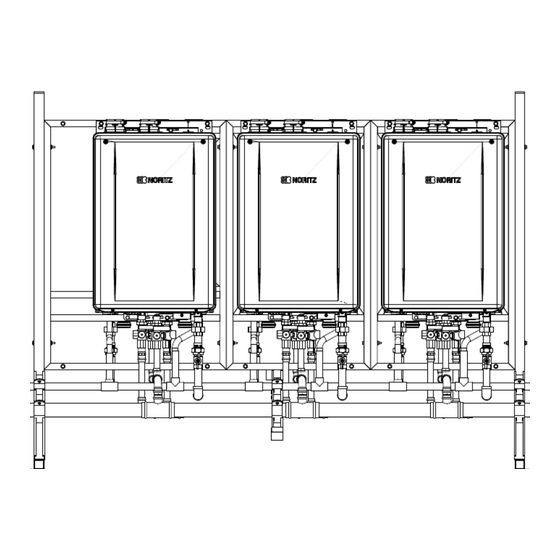
Page 31: Unit Drawing Illustration / Dimensions
3 Unit Drawing Illustration / Dimensions EXHAUST FLUE *All Units are in inches CR60-IM.v0429.4... -
Page 32: Cr60-Fs-4 Specifications
CR60-FS-4 Specifications BTU and Flow Rates for NCC199CDV (GQ-C3260WZ-FF US) Number of Tankless Water Heaters Max. Hot Water Capacity @ 30°F rise (GPM) 44.4 Max. Hot Water Capacity @ 70°F rise (GPM) 22.4 Minimum (Btuh) 18,000 Maximum (Btuh) 799,600 Model and Rack Specifications... -
Page 33: Unit Drawing Illustration / Dimensions
4 Unit Drawing Illustration / Dimensions *All Units are in inches CR60-IM.v0429.4... -
Page 34: Cr60-Fs-5 Specifications
CR60-FS-5 Specifications BTU and Flow Rates for NCC199CDV (GQ-C3260WZ-FF US) Number of Tankless Water Heaters Max. Hot Water Capacity @ 30°F rise (GPM) 55.5 Max. Hot Water Capacity @ 70°F rise (GPM) 28.0 Minimum (Btuh) 18,000 Maximum (Btuh) 999,500 Model and Rack Specifications... -
Page 35: Unit Drawing Illustration / Dimensions
5 Unit Drawing Illustration / Dimensions *All Units are in inches CR60-IM.v0429.4... -
Page 36: Cr60-Fs-6 Specifications
CR60-FS-6 Specifications BTU and Flow Rates for NCC199CDV (GQ-C3260WZ-FF US) Number of Tankless Water Heaters Max. Hot Water Capacity @ 30°F rise (GPM) 66.6 Max. Hot Water Capacity @ 70°F rise (GPM) 33.6 Minimum (Btuh) 18,000 Maximum (Btuh) 1,199,400 Model and Rack Specifications... -
Page 37: Unit Drawing Illustration / Dimensions
6 Unit Drawing Illustration / Dimensions *All Units are in inches CR60-IM.v0429.4... -
Page 38: Hoisting And Lifting Lugs
Hoisting and Lifting Lugs • The Floor Standing models come equipped with rings for hoisting, lifting, and moving. The hoisting cable lines to the lugs should be perpendicular at a 90° angle. It is recommended to use a spreader lifting bar for safety precaution. For total weight of the CR60, refer to the specification section of this manual. -
Page 39: Securing Floor Standing Cr60 Models
Securing Floor Standing CR60 Models • All mechanical components shall be anchored and installed in accordance with national and local codes including anchorage to building structures. • To secure all floor standing models, 7/16” diameter holes are pre-drilled in the base rail. Refer to the figure below for location of these holes. -
Page 40: Securing Commercial Water Heating System Wall Mount
Securing Commercial Water Heating System Wall Mount • Before mounting the CR60 to the wall, make sure the wall is capable of supporting the fully assembled weight of the CR60. • Consult a structural engineer for appropriate methods or structural analysis before attempting to wall mount the fully assembled CR60. - Page 41 Installing the CR60 with Optional Floor Support to Wall Mount Racks Each Noritz wall mounted rack comes with an optional floor support included with each purchase. The Noritz CR60 racks are designed to be installed with or without this bottom support. The optional floor support is supplied to ease the installation of the CR60 rack.
- Page 42 1. Lay the CR60 flat on a level surface with the water heaters facing up 2. Align end rails with side marked with “TOP” facing toward the wall hanging rack. Insert 3½” bolt with flat washer through clearance hole at bottom of wall hanging rack at locations and direction shown in the figure below.
- Page 43 5. Raise rack to upright position by lifting from the back. Do not attempt to lift by pulling the front. Rack is heavy. Recommended 2 person lift Rack may slide on legs while lifting. Take precaution to prevent the rack from sliding while attempting to raise the rack to the upright position.
- Page 44 Installing Wall Mounted Rack without Optional Floor Support 1. Determine the desired position of the top of the rack 2. Mark this dimension along the wall 3. Measure down 44.0 in. and install a 2x4 wood piece of length to match the CR60 rack. This 2x4 must be anchored at a maximum of every 18 in.
- Page 45 Relief Valve Piping • Each Noritz tankless water heater on the CR60 comes installed with an isolation valve and a pressure relief valve on the hot water outlet side. • The pressure relief valve shall be operated once a year to ensure that it is functioning properly and there is no obstruction.
-
Page 46: Freeze Prevention / Insulation
Freeze Prevention / Insulation • In normal operation, freezing is prevented within the device automatically unless the outside temperature without wind is below -30°F (-35°C) for indoor installation or -4°F (-20°C) for outdoor installations. • For models installed in an area where the outside temperature can approach freezing conditions of -30°F (-35°C) or outdoor -4°F (-20°C) or below, then additional protection measures must be used. -
Page 47: Rack Parallel Piping System
Rack Parallel Piping System CR60 • Multiple Noritz can be installed series. Refer to the following table for the maximum number of racks that can connected together. Rack Name Max Racks Total Quantity of Heaters CR60-WH-2 CR60-WH-3 CR60-FS-4 CR60-FS-5 CR60-FS-6 •... -
Page 48: Making Piping Connections
Making Piping Connections Once water flow and gas supply direction is determined, the opposite end of the supply manifold must be capped and checked for leaks. End caps shall be field supplied and be of the following materials: • Cold water line cap - Copper •... -
Page 49: Condensate Drain To Floor Or With Pump
Note: The neutralizer is NOT included in the Commercial Water Heating System package. The optional neutralizer can be purchased separately (Noritz Part# NT-20A). • The end of the drain pipe must not be submerged in water or blocked in any way. To ensure proper drainage, leave the end of the drain pipe open to the atmosphere. - Page 50 • Take measures to prevent the condensate drain lines from freezing (insulation, heat tape, electric heaters, etc.) as illustrated below if being installed outdoors or other unconditioned space. • If the water heater has been out of use for a long period of time, make sure that you fill the condensate trap with water.
-
Page 51: Water Treatment
Damage to the water heater as a result of water in excess of 12 gpg (200 mg/L) of hardness is not covered by the Noritz America Limited Warranty. Note: Water softeners may be regulated by the local water jurisdiction, consult with the manufacturer for code, sizing, and installation guidelines;... -
Page 52: Installation Of Gas Supply
3. Turn off the gas and do not smoke or have other ignition sources while working on the gas. 4. Do not turn on Noritz tankless water heater or gas line until all fumes are gone. 5. Check the rating plate for correct gas type and gas inlet pressure before connecting to the water heater. -
Page 53: Electrical Wiring
Electrical wiring The units on the CR60 are not pre-wired. Each water heater requires 120VAC, 60Hz power from a properly grounded circuit. For additional information please refer to the Water Heater Installation Manual and consult with a qualified electrician. • If using a power cord, plug it into a standard 3 prong 120VAC 60Hz properly grounded wall outlet. •... -
Page 54: Remote Controller
18 AWG wire up to 300 ft. Refer to the Water Heater Installation Manual for additional mounting instructions. • Only one remote controller is connected to the Noritz tankless water heater to monitor and control all the units. If two or more remote controllers are connected a malfunction will occur. - Page 55 • For additional information, refer to (SC-401-6M) Installation Manual for information such as remote initial setup (pg. 9), recirculation pump timer setup (pg. 13), system check button (pg. 15), maintenace monitors and additional settings (pg. 16). *The remote controller is not resistant to water, steam, chemcials, or UV rays. Store the remote in a location where it will not be exposed to these conditions.
-
Page 56: Multi System Controller
Multi System Controller • The CR60 comes pre-installed with a system controller for up to 6 units (SC-401-6M). • Each Noritz tankless water heater will be electronically connected with the multi system controller. CR60-IM.v0429.4... - Page 57 CR60-IM.v0429.4...
- Page 58 • The system controller is installed inside the rightmost unit denoted by a #1 sticker located on the front cover of the unit. • Each unit will have a numbered sticker on the front cover, ordered in a clockwise direction (Refer to diagram below).
-
Page 59: Final Checklist
Water Supply Water supply pressure is between 15-150 psi (103.4-1034 kPa) (Noritz recommends water pressure between 30-70 psi (207 – 483 kPa) for maximum performance. Installing a pressure regulating valve above 70 psi supply pressure can help to reduce water hammer) - Page 60 Unused end of the cold water and hot water supply pipes are capped Pressure relief valves are installed and piped in accordance with local building code If water heaters will not be placed into immediate service, water heaters are drained in accordance with procedure located in the appliance installation manual Condensate Drain Condensate drain is discharging condensate...
-
Page 61: Trial Operation
Trial Operation The installer should test operate the unit, followed by explaining to the customer how to use the unit, and give the owner this manual before leaving the installation site. Preparation steps. 1. Confirm the condensate trap is filled with approx. 10 oz. (280 mL) of water inside the exhaust (indoor installations). - Page 62 • If the water heater does not operate normally, refer to “Troubleshooting” in the Operation Manual. After the trial operation, clean the filter in the cold water inlet. • Use the remote controller to see the status of how many units are igniting. Shutdown Steps.
-
Page 63: Warranty For Tankless Units & Commercial Water Heater System Components
Warranty for Tankless Units & Commercial Water Heater System Components Warranty Registration Required * Warranty Period Period of Coverage (Date of Installation or 30 Days After Purchase) Labor Parts Heat Exchanger Tankless Water Heater 1 year 5 years 10 years Commercial Water Heater System Rack 1 year CR60-IM.v0429.4... - Page 64 CR60-IM.v0429.4...
- Page 65 CR60-IM.v0429.4...
Need help?
Do you have a question about the NCC199CDV and is the answer not in the manual?
Questions and answers