Cairn OPTOSPLIT II Setup Manual
Image splitter
Hide thumbs
Also See for OPTOSPLIT II:
- Instruction manual (22 pages) ,
- Troubleshooting manual (12 pages)

Related Manuals for Cairn OPTOSPLIT II


Summary of Contents for Cairn OPTOSPLIT II
- Page 1 OPTOSPLIT S e t g u i d e email: sales@cairn-research.co.uk tech@cairn-research.co.uk +44(0)1795 590140 www.cairn-research.co.uk...
- Page 2 Installing Filters into the Cairn Filter Cube The Cairn Filter Cube has spaces for two 25mm filters. These are held in place by locking rings which can be re- moved using the tool provided. To fit a filter, remove the locking ring and place the filter orientated so that the arrow points into the Cairn Filter Cube and towards the beamsplitter (correct for Chroma mirrors, please refer to us if using filters from a different manufacturer).
- Page 3 The filter cube mount will now be visible. The mount attached to the rear of the Cairn Filter Cube is de- signed to mate with the bracket on the internal wall of the Optosplit II so that the small handle on top of the cube will be facing out.
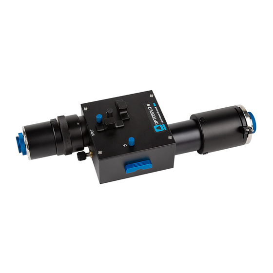
- Page 4 Image. Optosplit II: Key controls The Optosplit II uses a single control for adjusting image separation (Split Adjuster) and allows for different sized camera chips to be used. There are additional controls for refining the ROI, and centering the image.
- Page 5 OPTOSPLIT S e t g u i d e Optosplit II: Key controls table Control Description Vertical adjustment for the shorter wavelength image Vertical adjustment for the longer wavelength image Horizontal adjustment for the longer wavelength image Split Separates the two images horizontally.
- Page 6 S e t g u i d e Adjusting and Locking the Aperture The Optosplit II is supplied with an adjustable rectangular aperture that allows the user to determine the ROI both vertically and horizontally. Turn aperture handles Aperture adjusters...
- Page 7 To adjust the image towards one edge. trim control, loosen the clamp screw on the underside of the Optosplit II by a quarter of a turn in order to free the slider which controls the trim control.
- Page 8 Single channel (non-split) mode When dual splitting is not required, the OptoSplit II unit can be used in bypass mode, allowing the unit to remain in situ on the microscope whilst utilising the full camera chip to generate one image.
Need help?
Do you have a question about the OPTOSPLIT II and is the answer not in the manual?
Questions and answers