Advertisement
Quick Links
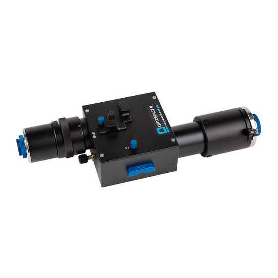
OPTOSPLIT II
This document details common technical queries reported by OptoSplit II users, how to troubleshoot, when to contact
Cairn and the information we require to provide help quickly to allow your research to continue.
Please refer to the OptoSplit II manual for guidance on setup.
For guidance on the OptoSplit II Bypass unit, please refer to supplementary documentation.
Useful information
Below is general guidance for all image-splitter troubleshooting:
•
Make a note of the OptoSplit serial number (found on the underside of the unit)
•
Please save troubleshooting images as Tiff files as these contain the most information.
•
Always save the raw data file (i.e. the non-overlaid dual channel images) rather than just the overlay.
•
Calibrate the unit (as per the set-up guide) and approach troubleshooting firstly with the calibration
cube supplied (consisting of a 50% / 50% mirror).
•
Make a detailed note of your emission filters and dichroic mirror. This includes the wavelength and the
specification of the items.
• Please note: we strongly recommend 2mm thick 'UltraFlat' dichroic mirrors (UF2) from Chroma for
minimal distortion when using the OptoSplit:
https://www.cairn-research.co.uk/products/chroma-filters-beamsplitters/
As UK Chroma distributors, we are happy to provide filter advice from our in-house experts, so
please do not hesitate to get in touch (tech@cairn-research.co.uk)
•
Please also let us know the model of the camera you are using and provide a photograph of the
OptoSplit in place on your microscope.
email: sales@cairn-research.co.uk tech@cairn-research.co.uk
+44(0)1795 590140 www.cairn-research.co.uk
T r o u b l e s h o o t i n g
Advertisement

Related Manuals for Cairn OPTOSPLIT II


Summary of Contents for Cairn OPTOSPLIT II
- Page 1 T r o u b l e s h o o t i n g This document details common technical queries reported by OptoSplit II users, how to troubleshoot, when to contact Cairn and the information we require to provide help quickly to allow your research to continue.
-
Page 2: Common Troubleshooting Issues
Locate the ‘Trim’ adjustment on the underside of the unit and loosen the clamp screw if required. • Slide the Trim adjustment until both images are evenly illuminated. • The Trim control can then be locked in place by re-tightening the clamp screw. email: sales@cairn-research.co.uk tech@cairn-research.co.uk +44(0)1795 590140 www.cairn-research.co.uk... - Page 3 Often symptomatic of a poorly aligned light source which has not been setup for Köhler illumi- nation, unrelated to the image splitter. Resolution • Remove the OptoSplit and optimise illumination settings on your microscope as per manufacturers instructions. • Once optimisation is complete, reattach the OptoSplit. email: sales@cairn-research.co.uk tech@cairn-research.co.uk +44(0)1795 590140 www.cairn-research.co.uk...
- Page 4 Identify which is the reflected (shorter wavelength) image by following the flow-chart below. • Always turn the split control anti-clockwise to separate the two images when using a standard OptoSplit II (please note, for the OptoSplit II bypass we recommend a clockwise split). email: sales@cairn-research.co.uk tech@cairn-research.co.uk +44(0)1795 590140 www.cairn-research.co.uk...
- Page 5 Flowchart for confirming camera orientation is correct and images are split correctly email: sales@cairn-research.co.uk tech@cairn-research.co.uk +44(0)1795 590140 www.cairn-research.co.uk...
- Page 6 Observations & likely cause • Rough, non-uniform feature in focus on diaphragm (aperture) blade • Most likely cause is dirt (highly magnified) on the aperture blades Resolution • Carefully clean the aperture using a lint-free lens tissue email: sales@cairn-research.co.uk tech@cairn-research.co.uk +44(0)1795 590140 www.cairn-research.co.uk...
- Page 7 Often, the fine focus adjustment is incorrectly used to focus the sample image, or to focus the camera image with the image observed via the eye-pieces (bifocality). Please only adjust the fine focus if the aperture blades are out of focus and note any adjustment should be minimal. email: sales@cairn-research.co.uk tech@cairn-research.co.uk +44(0)1795 590140 www.cairn-research.co.uk...
- Page 8 Focussing the Camera on the Aperture If the Optosplit II aperture is not in sharp focus, then adjust the fine focus on the camera as follows: • Set an aperture size of less than half the width of the camera frame.
- Page 9 Resolution • Refer to the OptoSplit II Set up Guide to familiarise yourself with key controls and follow ‘Adjusting the Position of the Images’ to re-align the two channels. • It is advisable to initially set up the two OptoSplit channels using the calibration cube included as standard with your unit.
- Page 10 ‘output tube’ length from the main OptoSplit body to the end of the camera c-mount is ~100mm for an LS unit. • Older OptoSplit II units can be upgraded to the LS format in the majority of cases. Please contact us for a quotation. •...
- Page 11 Four neutral density (ND) filters are routinely supplied, labelled as follows: 03GN25: 50% Transmittance 05GN25: 32% Transmittance 06GN25: 25% Transmittance 10GN25: 10% Transmittance • The ND filters are mounted in the auxiliary drop-in holders provided with each kit. Auxiliary Drop-in email: sales@cairn-research.co.uk tech@cairn-research.co.uk +44(0)1795 590140 www.cairn-research.co.uk...
- Page 12 Chromatic aberration results when the focal length changes depending upon the wavelength and is predominantly introduced by the objective lens. When imaging two wavelengths simultaneously, the phenomenon is observed using the OptoSplit II, rather than being caused by it. Resolution •...
Need help?
Do you have a question about the OPTOSPLIT II and is the answer not in the manual?
Questions and answers