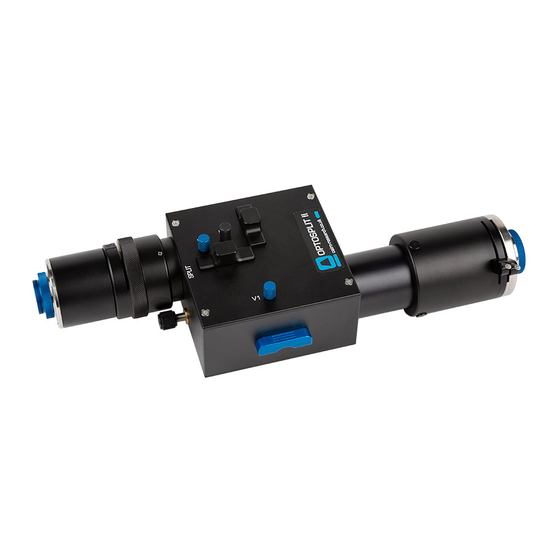
Summary of Contents for Cairn OptoSplit II
- Page 1 Free Phone: 08453301267 (UK only) Tel: +44 (0) 1795590140 Fax: +44 (0) 1795594510...
- Page 4 The Optosplit is supplied pre-aligned and centred, please refer to this manual before making any adjustments. When changing the Cairn Filter Cube, care should be taken not to touch any optical surfaces. If any lenses, lters, or mirrors are marked...
-
Page 5: Table Of Contents
Installation guide Installing Filters into the Cairn Filter Cube Installing Dichroic Mirrors into the Cairn Filter Cube Inserting the Cairn Filter Cube into the Optopsplit II Auxilliary Component Mounts Installing the Optosplit II in the Lightpath Operation of the Optosplit II... -
Page 6: Introduction
In conjunction with a research microscope and a suitable CCD camera the Cairn Optosplit II allows the researcher to do exactly this. The Cairn Optosplit II is usually supplied with a rectangular aperture to de ne a ROI and includes controls to allow the two images to be positioned accurately and conveniently within the camera frame. -
Page 7: Installation Guide
2.2. Always take extreme care when changing or adjusting the lter and mirror sets to avoid damage or soiling. If you purchased your Optosplit II with a full lter set pre-installed then you may wish to go to section 2.4. as the following may not be pertenant. -
Page 8: Installing Dichroic Mirrors Into The Cairn Filter Cube
Cairn Filter Cube is designed to mate with the bracket on the internal wall of the Optosplit II so that the small handle on top of the cube will be facing out. Once the Cairn Filter Cube is mounted successfully replace the access panel using the two handles. - Page 9 Mounting bracket Remove the access panel using the two handles. Mount the lter cube onto the brackect on the interior of the Optosplit II. Replace the access panel using the two handles. Page 4...
-
Page 10: Auxilliary Component Mounts
Installing the Optosplit II in the Light Path Before installing the Optosplit II unit it is important to rst set up the microscope, camera, and software to give a clear image of an object of less than half the size the camera frame. Ideally this should be a real sample with the appropriate optical properties for the installed lter set. -
Page 11: Operation Of The Optosplit
Operation of the Optosplit II The Optosplit II uses a single control for adjusting image seperation and allows for di erent sizes of samples to be used. There are additional controls for re ning the ROI, and centering the image. -
Page 12: Adjusting And Locking The Aperture
In order to adjust the ROI adjust each of the two levers on the input port of the Optosplit II until the desired area is de ned on the camera. If you wish to lock the aperture in place then tighten the levers by rotating them clockwise, and to loosen them rotate anti-clockwise. - Page 13 Split adjuster V1 adjuster Here we see the two superimposed images. Although your image may be monochromatic, colours have been used here to de ne the two images. Turning the Split control anti-clockwise will seperate the two images along the horizontal axis. Only small adjustments will be required when using the horizontal image seperation adjustment.
-
Page 14: Focussing The Camera On The Aperture
Focussing the Camera on the Aperture If the Optosplit II aperture is not in sharp focus, then adjust the ne focus on the camera as follows: Set an aperture size of less than half the width of the camera frame. -
Page 15: Centering Images On The Camera
Centering Images on the Camera When the Optosplit II is initially installed, or if the lter block goes out of alignment, the Optosplit II images can show visible aberrations, or in extreme cases only a single image may be observable for any setting of the separation control. -
Page 16: Image Optimisation (Trim Adjustment)
It is important to remember to re-tighten the clamp screw once the adjustment is complete. If the Optosplit II has been con gured into single channel (non-split mode) (see section 3.6) and Trim adjustment is required to compensate for vignetting being observed, it is likely the slider will need to be at the extreme of its range of movement to either end. -
Page 17: Single Channel (Non-Split) Mode
Single channel (non-split) mode When dual splitting is not required, the OptoSplit II unit can be used in bypass mode, allowing the unit to remain in situ on the microscope whilst utilising the full camera chip to generate one image. -
Page 18: Technical Summary
Technical Summary The Optosplit II uses a conventional dichroic mirror to seperate the light into two di erent spectral bands. This wavelength selection is usually augmented by the use of bandpass lters as shown below. Re ected image Transmitted image... - Page 19 110mm 261mm TRIM 110mm 261mm OPTOSPLIT II www.cairn-research.co.uk Page 14...
-
Page 20: Technical Support
Technical Support E-mail: tech@cairn-research.co.uk Web: http://www.cairn-research.co.uk Address: Cairn Research Graveney Road Faversham Kent ME13 8UP Telephone: +44 (0) 1795590140 Fax: +44 (0) 1795594510 Page 15 Page 15... - Page 21 In addition to designing and manufacturing our own products, we are also proud distributors for the following companies...


Need help?
Do you have a question about the OptoSplit II and is the answer not in the manual?
Questions and answers