Table of Contents
Advertisement
Advertisement
Table of Contents

Related Manuals for inbody 120


Summary of Contents for inbody 120
- Page 1 User’s Manual...
- Page 2 This manual might have typographical errors, and its content can be changed without a prior notice. InBody Co., Ltd shall not be liable for any errors, incidental, or consequential damages that occurred by not complying with the content of the User s Manual.
-
Page 3: Table Of Contents
C. Test Posture III. Transportation and Storage A. Repacking Instructions B. Transportation and Storage Environment IV. Frequently Asked Questions (FAQ) A. Regarding the InBody B. Regarding the InBody Test V. Others A. Exterior and Functions B. Safety Information C. Classification D. Specifications... -
Page 4: Inbody120 Installation
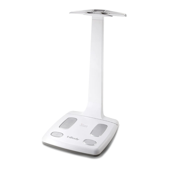
I. InBody120 Installation A. Product Components The InBody120 consists of the following components. Make sure all of the following components are present. * Please inspect each component of the InBody120 for defects prior to installation. InBody120 Adapter (DC 12V, 3.4A) 1 EA Power cord 1 EA Keypads Battery (AA) 4 EA... - Page 5 * Optional Equipments 1) InBody120 Stand InBody120 Stand 1 EA 2) Lookin’Body120 (Data Management Software) Lookin’Body120 CD 1 EA Lookin’Body Bluetooth Dongle (InBT-USB) 1 EA 3) Thermal Printer Thermal Printer 1 EA Thermal Printer Cable 1 EA Thermal Printer Paper 1 EA Thermal Printer Holder 1 EA Thermal Printer Screws 4 EA 45mm...
-
Page 6: Operating Environment
Never clean the hand and foot electrodes with liquid spray or detergent directly. The equipment may corrode • and/or malfunction if the liquid or detergent leaks inside. Use the InBody Tissue when cleaning the InBody120. * For inquires regarding the InBody Tissue, Please contact InBody. - Page 7 3. Separate the control handle and the footplate. 4. Connect the adapter ( ) to the power input port, which is located on the rear panel of the InBody120 ( ). Connect the adapter ( ) to the power cord ( ). Then, plug the power cord ( ) into a grounded 3-socket outlet. * The InBody120 can be used in connection with the data management software, Lookin’Body120.
- Page 8 Do not share the power source of the InBody120 with other electrical devices. This may affect the test results. Always use the specified adapter provided by InBody, as it is a part of the InBody120. Using other adapters •...
- Page 9 6. Follow the instructions below when using batteries. * When using batteries, the InBody120 will automatically power off when it is not in use for 2 minutes and 30 seconds. * The InBody120 will not automatically power off when connected with Lookin’Body120. * Thermal Results Sheet will only print when the InBody120 is plugged into an outlet.
-
Page 10: Initial Setup
D. Initial Setup 1. The InBody120 automatically starts booting when it is turned on. While booting, it performs a self weight calibration. * While booting (about 7 seconds), make sure there is nothing on top of the footplate. Please do not stand on the footplate, or place objects on the footplate. - Page 11 2) Units: Setup the measuring units when the following LCD appears. The settings will be applied to the LCD result screen and the Thermal Results Sheet. a. Select ‘2 Ut (2. Measuring Unit Configuration)’, using the [▲] or [▼] button and press the [Enter] button to configure. b. Set the measuring units using the [▲] or [▼] button. Weight unit: kg, height unit: cm Weight unit: lbs, height unit: ft.
-
Page 12: Connecting Lookin'body120
• between the equipment and the computer, the weaker the Bluetooth connection will be. Please make sure there is minimal to no interference, such as walls, between the computer and the InBody. • 1) Press the [ On/Off ] button to turn on the InBody120. - Page 13 4) Lookin’Body120 willl start to search nearby InBody via Bluetooth. Select the appropriate InBody120 to connect. * If having trouble selecting the appropriate InBody120, check your InBody’s serial number on the bottom of the InBody120. Serial number Bottom of the InBody120...
- Page 14 A corresponding Bluetooth icon will also appear on the LCD screen of the InBody120. Bluetooth icon 6) Click the [Register New] button to register new member and proceed to the InBody Test. * For more information about Lookin’Body120, please refer to the Lookin’Body120 User’s Manual.
- Page 15 In order to print a Thermal Results Sheet, an InBody120 compatible Thermal Printer is required. * Always connect a Thermal Printer from InBody. 1) Open the Thermal Printer lid. Insert a roll of the Thermal Printer Paper in the direction illustrated.
- Page 16 4) Turn on a Thermal Printer. The Thermal Printer will print a sample results sheet when properly connected. * When properly connected, the Thermal Results Sheet will automatically print after each InBody Test. To re-print the last test result, press and hold the [Enter] button for over 3 seconds.
-
Page 17: Optional Installation Instructions
F. Optional Installation Instructions 1. InBody120 Stand 1) Separate the control handle from the footplate. Insert the InBody120 Stand into the designated spot as shown in the illustration below. 2) After fitting the InBody120 Stand into the designated spot, press down firmly to secure it in place. InBody120 Stand Designated spot 3) Feed the control handle through the bottom of the cable protector, then place the handle on the handle holder. - Page 18 2. Thermal Printer The Thermal Printer can be installed onto the InBody120 Stand. 1) Align the screw holes on the back of the Thermal Printer with the Thermal Printer Holder and insert the screws from the Thermal Printer Holder to the Thermal Printer as illustrated below, then tighten. Screw holes Thermal Printer Holder 2) Insert the Thermal Printer Holder Hook into the designated opening on the side of the cable protector...
- Page 19 4) Tighten the screw from the Thermal Printer Holder to the cable protector as illustrated below. Holder screw 5) Plug the serial cable provided with the Thermal Printer into the serial port on the rear panel of the InBody120. Plug the InBody120 Stand connector to back of the InBody120 Stand as illustrated below. * The InBody120 Stand connector of the Thermal Printer cable will minimize the electrical shock through the Thermal Printer.
-
Page 20: Maintenance
6) Plug the Thermal Printer connecting part to the Thermal Printer. G. Maintenance NOTE DANGER Caution 참 조 주 의 참 고 주 의 Do not bend the handles of the hand electrode. • Do not place any objects on the footplate. •... -
Page 21: Inbody Test
Children and people with limited mobility should be supervised or assisted when attempting to test on the InBody. • After an individual with any kind of contagious disease or infection tests on the InBody, use an InBody Tissue • to clean the equipment. -
Page 22: Test Instructions
3. Input height by using the [▲] or [▼] buttons, then press the [ Enter ] button. 4. Maintain proper posture to take the test. * Refer to ‘C. Test Posture.’ for the proper posture. 5. The InBody Test will begin. - Page 23 6. When the test is completed, the results will be shown on screen. Results: Weight, Body Fat (Percent Body Fat), Muscle (Skeletal Muscle Mass), and BMI * A Thermal Results Sheet will be printed if a Thermal Printer is connected. Always use a Thermal Printer from InBody. * The printer icon ( ) will appear when printing.
-
Page 24: Test Posture
C. Test Posture The examinee must maintain proper posture to have accurate test results. * The test will proceed when there is good electrical contact. Your arms must not touch the sides of your body. It is strongly recommended to wear shirts with sleeves. -
Page 25: Transportation And Storage
Caution 참 조 주 의 참 고 주 의 Always use the protective packing materials provided by InBody when repacking. • B. Transportation and Storage Environment The InBody120 should be transported or stored under the following conditions. Temperature range -10 ~ 70˚C (14 ~ 158˚F ) -
Page 26: Frequently Asked Questions (Faq)
Insert the power cord completely into the adapter. The problem may occur if you are using the power adapter that is not • provided by InBody. Always connect a power adapter (DC 12V, 3.4 A) provided by InBody. Power adapter Power cord Batteries may need to be replaced. - Page 27 Measuring units must be properly set. To change measuring unit, please go • to ‘Setup’ by pressing the [▲] and [▼] buttons for 3 seconds. Restart the InBody. Remove all objects on the footplate during the restart. • The InBody Test has It may be due to poor electrical contact with the body.
-
Page 28: Regarding The Inbody Test
• harmful to the body? that is not harmful to the body. The safety of the InBody has been tested and proven. The InBody products have been approved for medical use by the CE and all over the world. Many medical institutions around the world are actively using the InBody. -
Page 29: Others
V. Others * The InBody120 is manufactured according to the quality management procedure of InBody. InBody complies with the ISO9001 and ISO13485 which are international quality management systems. * This equipment satisfies the IEC60601-1(EN60601-1), an international safety standard for electronic medical equipment. This equipment also satisfies the IEC60601-1-2(EN60601-1-2), an international standard for electromagnetic conformity. A. Exterior and Functions The followings are the names and functions of each part of the InBody. - Page 30 Power input port: Used for connecting to the power adapter. 9-pin serial port (Female, RS-232C): Used for connecting the InBody120 to a Thermal Printer. * Only compatible with a InBody Thermal Printer. 4. Bottom Part Battery tray: Used for inserting batteries.
-
Page 31: Safety Information
B. Safety Information Indicators 9-pin serial port (Female, RS-232C) Safety Symbols Dangerous High Voltage Warning, Caution BF Type Equipment Adapter Power On Power Off Etc. Symbols European Conformity Serial number 0120 0120 0120 Manufacturer Direct current Authorized representative in the 0120 Operating instructions 0120... - Page 32 Follow instructions for use Suivez les instructions d’utilisation WARNING Electric shock hazard – do not dismantle. Dismantling will void the warranty. AVERTISSEMENT Risque de choc électrique - ne pas démonter. Le démontage annulera la garantie. DANGER Do not use this equipment with electrical medical device such as a pacemaker. Ne pas utiliser cet équipement avec des appareils médicaux électriques comme un stimulateur cardiaque.
-
Page 33: Classification
Results Interpretation QR Code Impedance (Each frequency, Each segment) Name, Address, and Contact Information can be shown on the Thermal Results Sheet Logo and InBody Results Sheet (via data management software Lookin’Body120) Digital Results LCD Monitor, Data management software Lookin’Body120... - Page 34 Thermal Results Sheet, InBody Results Sheet Types of Result Sheets (via data management software Lookin’Body120) Sound Guidance Provides beeping sound for test in progress, test complete, and saved Setup changes. Setup Setup: Language and Measuring Units Configuration on the Thermal Results Sheet Applied Rating Current 150µA (± 50µA) Battery DC 6V (1.5V AA, 4 EA)
-
Page 35: Emc Declaration
E. EMC declaration The InBody120 is intended for use in the electromagnetic environment specified below. The customer or the user of the InBody120 should assure that it is used in such an environment. Electromagnetic emissions Emissions test Compliance Electromagnetic environment The InBody120 uses RF energy only for its internal function. RF emissions CISPR 11 Group 1 Therefore, its RF emissions are very low and are not likely to cause any interference in nearby electronic equipment. - Page 36 Power frequency Power frequency magnetic fields should be at (50/60 Hz) 3 A/m 3 A/m levels characteristic of a typical location in a magnetic field typical commercial or hospital environment. IEC 61000-4-8 NOTE UT is the a.c. mains voltage prior to application of the test level. IEC 60601 Immunity test Compliance level Electromagnetic environment...
- Page 40 ©2018 InBody Co., Ltd. All rights reserved. BM-ENG-F3-E-180701...
Need help?
Do you have a question about the 120 and is the answer not in the manual?
Questions and answers