Table of Contents
Advertisement
Advertisement
Table of Contents

Related Manuals for Cisco Catalyst 9800-L Series


Summary of Contents for Cisco Catalyst 9800-L Series
- Page 1 Cisco Catalyst 9800-L Wireless Controller Hardware Installation Guide First Published: 2019-04-04 Last Modified: 2020-11-30 Americas Headquarters Cisco Systems, Inc. 170 West Tasman Drive San Jose, CA 95134-1706 http://www.cisco.com Tel: 408 526-4000 800 553-NETS (6387) Fax: 408 527-0883...
- Page 2 Cisco has more than 200 offices worldwide. Addresses and phone numbers are listed on the Cisco website at www.cisco.com/go/offices. Cisco and the Cisco logo are trademarks or registered trademarks of Cisco and/or its affiliates in the U.S. and other countries. To view a list of Cisco trademarks, go to this URL: https://www.cisco.com/c/en/us/about/legal/trademarks.html.
-
Page 3: Table Of Contents
Related Documentation viii C H A P T E R 1 Overview of Cisco Catalyst 9800-L Wireless Controller Summary of Cisco Catalyst 9800-L Wireless Controller Features Platform Components Cisco Catalyst 9800-L Wireless Controller Front Panel Front Panel LEDs: Definitions of States... - Page 4 Power Up and Initial Configuration Powering Up the Controller Performing the Initial Configuration on the Controller Using the Cisco IOS-XE CLI - Cisco Setup Command Facility Day 0 CLI Wizard for the Controller Day 0 Web UI Wizard for the Controller Using the Cisco IOS-XE CLI—Manual Configuration...
- Page 5 Contents Power Specifications Cisco Catalyst 9800-L Wireless Controller Hardware Installation Guide...
- Page 6 Contents Cisco Catalyst 9800-L Wireless Controller Hardware Installation Guide...
-
Page 7: Preface
• Related Documentation, on page viii About this Guide This guide is designed to help experienced network administrators install and minimally configure Cisco Catalyst 9800-L Wireless Controller. Conventions This document uses the following conventions for notes, cautions, and safety warnings. Notes and cautions contain important information that you should know. -
Page 8: Related Documentation
Preface Related Documentation Related Documentation • For information about the Cisco Catalyst 9800-L Series Wireless Controllers, see: https://www.cisco.com/c/en/us/support/wireless/catalyst-9800-series-wireless-controllers/ tsd-products-support-series-home.html • For information about the Regulatory Compliance and Safety Information Cisco Catalyst 9800-L Wireless Controller, see: https://www.cisco.com/c/dam/en/us/td/docs/wireless/controller/9800/9800-L/regulatory/ RCSI-0419-book.pdf Cisco Catalyst 9800-L Wireless Controller Hardware Installation Guide... -
Page 9: Overview Of Cisco Catalyst 9800-L Wireless Controller
Overview of Cisco Catalyst 9800-L Wireless Controller Cisco Catalyst 9800-L Wireless Controller is the first low-end controller that provides a significant boost in performance and features from Cisco 3504 Wireless Controller. The following are the two variations of the controller: •... -
Page 10: Summary Of Cisco Catalyst 9800-L Wireless Controller Features
Overview of Cisco Catalyst 9800-L Wireless Controller Summary of Cisco Catalyst 9800-L Wireless Controller Features Summary of Cisco Catalyst 9800-L Wireless Controller Features Table 1: Cisco Catalyst 9800-L Wireless Controller Features Feature Description Chassis Height One rack-unit (1RU) Throughput 5 Gbps... -
Page 11: Platform Components
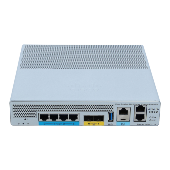
Overview of Cisco Catalyst 9800-L Wireless Controller Platform Components Platform Components Cisco Catalyst 9800-L Wireless Controller Front Panel Figure 3: Cisco Catalyst 9800-L Wireless Controller Front Panel View Table 2: Cisco Catalyst 9800-L Wireless Controller Front Panel Components Service Port LED Redundancy Port LED Service Port (SP) (RJ-45) for out-of-band management Redundancy Port (RP) (RJ-45). - Page 12 1500 VAC rms isolation (per the 802.3 specification) is met between chassis ground and any Ethernet signal. Note The ports can be used for infra-switch connection using multiple an AP-Manager or data interface. Cisco Catalyst 9800-L Wireless Controller Hardware Installation Guide...
-
Page 13: Front Panel Leds: Definitions Of States
Blinking Green System boot Controller error. For example, an internal voltage error exists. Table 4: Alarm LED Indicators Color Description Blinking Green Controller image upgrade Amber Controller status activity, such as firmware upgrade Cisco Catalyst 9800-L Wireless Controller Hardware Installation Guide... -
Page 14: Cisco Catalyst 9800-L Wireless Controller Rear Panel
Note The Cisco Catalyst 9800-L Wireless Controller has an external power adapter. The Alarm Bell LED is illuminated red, if the the 10-G uplink ports are not connected to the switch. This does not mean a system or hardware failure. -
Page 15: Preparing Your Site For Installation
• For 10/100/1000 fixed ports, the cable length from a switch to a connected device cannot exceed 328 feet (100 meters). • Clearance to the front and rear panel meets these conditions: • Front-panel LEDs can be easily read. • Access to ports is sufficient for unrestricted cabling. Cisco Catalyst 9800-L Wireless Controller Hardware Installation Guide... - Page 16 Connect the unit only to DC power source that complies with the Safety Extra-Low Voltage (SELV) requirements in IEC 60950 based safety standards. Statement 1033. Warning Class 1 laser product. Statement 1008 Cisco Catalyst 9800-L Wireless Controller Hardware Installation Guide...
-
Page 17: Unpacking And Inspecting The Controller
IEC 60825-1 Ed. 3 as described in Laser Notice No. 56, dated May 8, 2019. Statement 1255. Unpacking and Inspecting the Controller Follow these steps to unpack the Cisco Catalyst 9800-L Wireless Controller and prepare it for operation: Procedure Step 1 Remove the controller from its container and save all the packaging material. -
Page 18: Package Contents
• One Power supply and power cord (power cord option configurable) • Optional licenses will be pre-installed on controller at factory, if selected • Cisco Catalyst 9800-L Wireless Controller software pre-loaded on the controller (software option configurable) • Four adhesive rubber feet pieces... - Page 19 Statement 1024. Warning This product relies on the building’s installation for short-circuit (overcurrent) protection. Ensure that the protective device is rated not greater than 20A. Statement 1005. Cisco Catalyst 9800-L Wireless Controller Hardware Installation Guide...
- Page 20 Preparing Your Site for Installation Choosing a Physical Location Cisco Catalyst 9800-L Wireless Controller Hardware Installation Guide...
-
Page 21: Installing The Cisco Catalyst 9800-L Wireless Controller
C H A P T E R Installing the Cisco Catalyst 9800-L Wireless Controller This chapter describes how to install the Cisco Catalyst 9800-L Wireless Controller. Warning IMPORTANT SAFETY INSTRUCTIONS This warning symbol means danger. You are in a situation that could cause bodily injury. Before you work on any equipment, be aware of the hazards involved with electrical circuitry and be familiar with standard practices for preventing accidents. - Page 22 Peel off the rubber feet from the black adhesive strip and press them adhesive-side down onto the bottom four corners of the controller, see the figure below: Figure 6: Attaching the Rubber Feet Step 4 Place the controller right-side up on a flat, smooth, secure surface. Cisco Catalyst 9800-L Wireless Controller Hardware Installation Guide...
-
Page 23: Mounting The Controller On A Wall
Place the controller onto the mounting screws and slide it down until it lock into place, as shown in figure below: The front panel of the controller should be facing down. Note Cisco Catalyst 9800-L Wireless Controller Hardware Installation Guide... - Page 24 • Connecting the Controller Console Port • Securing the Power Adapter Cable • Connecting to the Network Step 5 For configuration instructions about using the CLI setup program, see the (Link to Running the Bootup script section). Cisco Catalyst 9800-L Wireless Controller Hardware Installation Guide...
-
Page 25: Rack Mounting The Controller
Slide the Cisco Catalyst 9800-L Wireless Controller in position such that the 4-tray tabs align and latch into the bottom of the unit as it is pushed in place. The front of the Cisco Catalyst 9800-L Wireless Controller should be flush against the front edge of the tray. A nylon latch in the center of the tray snaps into and locks the Cisco Catalyst 9800-L Wireless Controller in place. - Page 26 Installing the Cisco Catalyst 9800-L Wireless Controller Rack Mounting the Controller Figure 8: Placing the Controller on the Rack Mount Tray Cisco Catalyst 9800-L Wireless Controller Hardware Installation Guide...
- Page 27 Installing the Cisco Catalyst 9800-L Wireless Controller Rack Mounting the Controller Figure 9: Close-up View of Center Latch Securing Controllers in a Rack Step 3 Remove power supply baffle in rear tray. Baffles secure with tabs circled. Cisco Catalyst 9800-L Wireless Controller Hardware Installation Guide...
- Page 28 Re-install and secure tabs on power supply baffle, coil extra cables, and locate them under the baffle. Note This is an hot air baffle. Step 7 Attach the rack mount tray to the rack using the supplied screws and brackets, as shown in figures below: Cisco Catalyst 9800-L Wireless Controller Hardware Installation Guide...
- Page 29 Installing the Cisco Catalyst 9800-L Wireless Controller Rack Mounting the Controller Figure 11: Attaching the Rack Mount Tray to a Front Post Rack Cisco Catalyst 9800-L Wireless Controller Hardware Installation Guide...
- Page 30 Installing the Cisco Catalyst 9800-L Wireless Controller Rack Mounting the Controller Figure 12: Installing the Rack Mount Tray to a Center Post Rack Install the center mount brackets to both sides of the tray. Note Cisco Catalyst 9800-L Wireless Controller Hardware Installation Guide...
- Page 31 Step 8 (optional): If required install the rear rack mount bracket for additional stability on four-post racks. Include optional orderable rear rack mount adapter kit: C4948E-BKT-KIT= C49xxE front and rear mount brackets. Cisco Catalyst 9800-L Wireless Controller Hardware Installation Guide...
-
Page 32: Connecting The Controller Console Port
Step 2 If you are using a standard Cisco DB-9 console cable, connect the end of the cable with the DB-9 connector (or USB Type-A) to the terminal or PC. If your terminal or PC has a console port that does not accommodate a DB-9 connector, you must provide an appropriate adapter for that port. -
Page 33: Installing A Security Lock
The controller has a security slot on the back panel. You can install an optional customer-supplied Kensington lock, such as the type that is used to secure a laptop computer, to secure the controller. See the "Cisco Catalyst 9800-L Wireless Controller Rear Panel" section for the location of the security lock. - Page 34 Installing the Cisco Catalyst 9800-L Wireless Controller Installing a Security Lock Cisco Catalyst 9800-L Wireless Controller Hardware Installation Guide...
-
Page 35: Installing The Power Supply
The 110W AC power supply is an autoranging unit that supports input voltages between 100 and 240 VAC. The power supply adapter uses an 18- AWG power cord for connection to an AC power outlet. Cisco Catalyst 9800-L Wireless Controller Hardware Installation Guide... - Page 36 Installing the Power Supply Overview on Power Supply Figure 14: 110W AC Power Cord A 6-pin latching DC connector supplies power to the controller. Figure 15: 6-Pin Latching DC Connector Cisco Catalyst 9800-L Wireless Controller Hardware Installation Guide...
-
Page 37: Installation Guidelines
Translations of the warning statements appear in the RCSI guide on Cisco.com. Observe these guidelines when installing a power supply: • A power supply that is only partially connected to the controller can disrupt the system operation. Cisco Catalyst 9800-L Wireless Controller Hardware Installation Guide... -
Page 38: Installing An Ac Power Supply
Confirm that the power supply PS OK LED is green. Finding the Power Supply Serial Number If you contact Cisco Technical Assistance regarding a power supply, you need to know the serial number. You can find the serial number printed on the external power adapter. -
Page 39: Power Up And Initial Configuration
Complex configuration procedures are beyond the scope of this publication and can be found in the modular configuration and command reference publications in the Cisco IOS software configuration documentation set that corresponds to the software release installed on your Cisco hardware. •... -
Page 40: Performing The Initial Configuration On The Controller
Performing the Initial Configuration on the Controller Performing the Initial Configuration on the Controller Using the Cisco IOS-XE CLI - Cisco Setup Command Facility The setup command facility prompts you to enter the information that is needed to configure a controller quickly. -
Page 41: Day 0 Cli Wizard For The Controller
Basic management setup is now complete. At this point, it is possible to save the above and continue wireless setup using the webUI (for this, choose 'no' below) Would you like to continue with the wireless setup? [yes]: yes This prompt is not applicable for 17.4 release. Note Cisco Catalyst 9800-L Wireless Controller Hardware Installation Guide... - Page 42 'no' below) Would you like to continue with the wireless setup? [yes] Step 12 Choose the deployment mode: Choose the deployment mode 1. Standalone Cisco Catalyst 9800-L Wireless Controller Hardware Installation Guide...
- Page 43 Enter hours offset from UTC (-23,23): 5 Enter mins offset from UTC (0,59) [0]: 30 Step 18 [Optional] Configure the expected client density: Configure Wireless client density? [yes]: Choose the client density 1. Low Cisco Catalyst 9800-L Wireless Controller Hardware Installation Guide...
- Page 44 Please choose the security type: 1. Webauth 2. Authbypass 3. Consent 4. Webconsent Enter the security type: Step 22 [Optional] Configure a virtual IP address. The recommended virtual IP address is 192.0.2.1. Cisco Catalyst 9800-L Wireless Controller Hardware Installation Guide...
- Page 45 RP-RP For information on HA pairing types, see Part: High Availability (High Availability > Information Note About Redundancy Management Interface) in Cisco Catalyst 9800 Series Wireless Controller Software Configuration Guide, Cisco IOS XE Bengaluru 17.4.x. High Availability configuration Please choose the HA pairing type 1.
-
Page 46: Day 0 Web Ui Wizard For The Controller
The hostname used in CLI prompts the default configuration filenames. If you do not configure the controller hostname, the controller uses the factory-assigned default hostname WLC. Procedure Command or Action Purpose Step 1 enable Enables privileged EXEC mode. Cisco Catalyst 9800-L Wireless Controller Hardware Installation Guide... -
Page 47: Configuring The Enable And Enable Secret Passwords
For more information, see the Configuring Passwords and Privileges chapter in the Cisco IOS Security Configuration Guide. Also see the Cisco IOS Password Encryption Facts tech note and the Cisco Guide to Harden Cisco IOS Devices tech note. -
Page 48: Configuring The Console Idle Privileged Exec Timeout
For more information on configuring the console line, see the Cisco IOS Configuration Fundamentals and Network Management Configuration Guide. In particular, see the Configuring Operating Characteristics for Terminals and Troubleshooting and Fault Management chapters. -
Page 49: Completing The Configuration
0 30 Completing the Configuration When using the Cisco setup command facility, and after you have provided all the information requested by the facility as described in Using the Cisco setup Command Facility section, the final configuration appears. To complete your controller configuration, follow these steps. -
Page 50: Gigabit Ethernet Management Interface Overview
• The interface provides a way to access the controller even if forwarding interfaces are not functional, or the Cisco IOS is down. • The management Ethernet interface is part of its own VRF. See the Cisco Catalyst 9800 Series Wireless Controller Software Configuration Guide for more details. - Page 51 For comprehensive configuration information on Gigabit Ethernet interfaces, see the Configuring LAN Interfaces chapter of the Cisco IOS Interface and Hardware Component Configuration Guide. For information on the interface numbering, see the Cisco Catalyst 9800 Series Wireless Controller Software Configuration Guide.
-
Page 52: Saving Your Controller Configuration
Note To aid file recovery and minimize downtime in case of file corruption, we recommend that you save backup copies of the startup configuration file and the Cisco IOS-XE software system image file on a server Note To avoid losing work you have completed, be sure to save your configuration occasionally as you proceed. -
Page 53: Powering Off The Controller Safely
• show configuration—Helps verify if you have configured the correct hostname and password. After you have completed and verified the initial configuration, the specific features and functions are ready to be configured. See the Cisco Catalyst 9800 Series Wireless Controller Software Configuration Guide. Powering Off the Controller Safely Before you begin We recommend that before turning off all power to the chassis, you issue the reload command. - Page 54 Powering Off the Controller Safely Last reset cause: LocalSoft The values of MSR 0x198h = 00001400 and MSR 0x199h = 00001400 for KATAR ME is in reserved state C9800-L-X-K9 platform with 16777216 Kbytes of main memory Cisco Catalyst 9800-L Wireless Controller Hardware Installation Guide...
-
Page 55: License Information
-------------------------------------------------------------------------------- C9800-L xxxxxxxxxxx C9800-L:xxxxxxxxxxx Viewing the Cisco IOS License Level Use the show version command to determine the Cisco IOS license level in the controller. Example: WLC# show version | section License Cisco Catalyst 9800-L Wireless Controller Hardware Installation Guide... - Page 56 License Type: Smart License is Indicates the type of license that is used. permanent This example shows that the Cisco Smart license is used that provides floating licenses for your user account. Other license types could be: Permanent (purchased) license or an Evaluation 60-day license.
-
Page 57: Appendix A Controller Specifications
32° F to 104° F (0° C to 40° C) Temperature Note The maximum temperature is derated by 1.0° C for every 1000 ft (305 m) of altitude above sea level. Storage Humidity 0% to 95% RH non-condensing Cisco Catalyst 9800-L Wireless Controller Hardware Installation Guide... - Page 58 This is calculated as follows: • 110W@12V Adapter C9800-AC-110W Table 14: Heat Dissipation and Power Consumption Specifications Description Specification Maximum heat dissipation (with 2-ports .3at) 48 W Maximum power consumption (with 2-ports .3at) 98 W Cisco Catalyst 9800-L Wireless Controller Hardware Installation Guide...
Need help?
Do you have a question about the Catalyst 9800-L Series and is the answer not in the manual?
Questions and answers