Cisco 5520 Deployment Manual
Lan controller
Hide thumbs
Also See for 5520:
- Installation instructions manual (10 pages) ,
- Troubleshooting manual (23 pages)

Related Manuals for Cisco 5520


Summary of Contents for Cisco 5520
-
Page 1: Table Of Contents
Link Aggregation (LAG) Inter-Platform Mobility and Guest Anchor Support Infrastructure Multicast New Mobility and MC Support Look and Feel of the Cisco 5520 Wireless LAN Controller Out of Band Management on Service Port Local EAP Support Wired Guest Access Support... - Page 2 Licensing...
-
Page 4: Cisco 5520 Wireless Lan Controller Deployment Guide
Product Overview The existing Cisco 5500 series controller scales up to 500 APs, 7,000 clients, and 8 Gbps maximum throughput. The explosion of mobile clients in enterprise empowered by bring your own device (BYOD), the deployment of wireless in mission-critical applications,... -
Page 5: Cisco 5520 Controller Key Attributes
AP scale, client scale, and higher throughput. The Cisco Unified Wireless Network Software Release 8.1 addresses these key challenges. Release 8.1 delivers the new Cisco 5520 wireless controller with support for 20 Gbps throughput, 1500 APs, and 20,000 clients to ensure better performance and scale for business critical networks. - Page 6 • Support of all AP modes of operation (Local, FlexConnect, Monitor, Rogue Detector, Sniffer, Bridge, and Flex+bridge) • Right to Use (RTU) licensing for ease of license enablement and ongoing licensing operations The following table shows the Cisco Enterprise Campus Controllers comparison at a glance: Table 2: Cisco Enterprise Campus Controllers comparison...
-
Page 7: Ap Platform Support
• 1700, 2700, 3700 • OEAP 600 • 702I, 702W • Cisco 891 series integrated services router and Cisco 881 series integrated services router • 1530, 1552WU, 1550, 1570 • 1040, 1140, 1260 support extended to 8.1 with 8.0 parity... -
Page 8: Platform Components
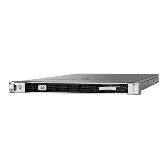
Cisco 5520 WLC Front Panel View Cisco 5520 wireless LAN controller supports several buttons, LED indicators, and a KVM connector on the front panel. It also includes a power button and Locator LED button, along with the following LEDS: System status, PSU status, Fan status, Network LED, and Temperature LED. - Page 9 • One of N fans has a fault Amber Blinking Critical fault state • Two or more fans has a fault Adaptive fan speed to control noise issues seen with 5520 FCS hardware is introduced in release version Note 8.1.131.0.
- Page 10 Temperature Status LED Indicator The temperature status LED is located on the front panel and indicates whether or not the system is operating within acceptable temperature limits. Table 6: Temperature Status LED Indicator LED Indicator Color Function Bi-color Yellow Temperature Status (Amber) State Decode...
- Page 11 Network Link LED Indicator The network LED is located on the front panel and indicates if any of the on-board networking ports are connected and operating. Table 8: Network Link LED Indicator LED Indicator Color Function Single Color Network Link Status Green State Decode...
- Page 12 Cisco 5520 WLC Rear Panel View The rear panel has the following interfaces: 1 Two Type A 3.0 USB ports 2 IMC port 10/100/1000 Base-T To setup the CIMC interface: • Connect the CIMC cable. • To enable DHCP to set the IP, use the command imm dhcp enable.
- Page 13 Note CIMC web interface is for advanced debugging for TAC and escalation use only. Changing of settings in the CIMC by customer can cause adverse impact on controller software and functionality. 3 SerialCOM connector — Standard RS-232 Serial COM port using RJ-45 connector 4 Ethernet service port (SP) —...
- Page 14 It is recommended to have all ports as either 10 G or 1 G. In case they are different, port 1 SFP determines the mode of operation and functionality on the other SFPs may not work. Table 9: Functionality of Cisco 5520 WLC when OIR occurs Hot Swap of SFP/SFP+...
-
Page 15: Sfp Support
10G to 1G Cisco 5520 WLC requires reboot between 10G and 1G 10G to 10G No reboot required SFP Support Network ports for 5520 WLC support the following Cisco SFP/SFP+ modules: • GLC-T • SFP-10G-SR • SFP-10G-LR • SFP-10G-LRM • SFP-H10GB-CU1M •... -
Page 16: Image Specifications
High Availability Stateful Switchover (SSO) model provides a Box-to-Box redundancy with one controller in active state and a second controller in hot standby state. The SSO model monitors the health of the active controller via a redundant (HA) port. Cisco 5520 wireless LAN controller has a failover RP Port. -
Page 17: Customer Replaceable Units
It is recommended to connect to a VSS pair and spread the links in each port-channel between the two physical switches to prevent a WLC switchover upon a failure of one of the VSS switches. Customer Replaceable Units Cisco 5520 wireless LAN controller has a minimal amount of separate orderable items, including all of the following:... -
Page 18: Link Aggregation (Lag)
Multicast support is enabled in the Cisco 5520 controller with the following restrictions: • If all APs on the 5520 controller are configured in Local mode, Multicast-Multicast will be the default mode and all features are supported (for example, VideoStream). -
Page 19: New Mobility And Mc Support
Look and Feel of the Cisco 5520 Wireless LAN Controller The Cisco 5520 controller enables console redirect by default with baud rate 9600, simulating a VT100 terminal with no flow control. The 5520 Controller has the same boot sequence as existing controller platforms. - Page 23 Monitoring and Best Practices This platform supports the Monitoring Dashboard and the Upgrade audit workflow view.
- Page 24 The following screenshot is the Best Practices Audit workflow page. Management Web UI The management web interface has the same look and feel as existing Cisco wireless LAN controllers.
-
Page 26: Out Of Band Management On Service Port
Out of Band Management on Service Port Starting release 8.2 the Service Port capability on the Cisco 5520 Wireless LAN Controller has been enhanced to support the following management services: • HTTP/HTTPS web-based access • SNMP polling v2 and v3 •... - Page 27 Service Port Configuration The IP address assigned to the service port must be in a non-routable subnet different from the Management subnet. It can be assigned dynamically or statically as shown in the configuration below. There is no change in the service port configuration itself and the commands below are for your reference.
-
Page 28: Local Eap Support
Local EAP Support Starting Software release 8.2, Cisco 5520 Wireless LAN Controller supports the Local EAP functionality natively on the controller. Local EAP is an authentication method that allows users and wireless clients to be authenticated locally on the controller. It is designed for use in remote offices that want to maintain connectivity to wireless clients when the backend system becomes disrupted or the external authentication server goes down. - Page 29 License Agreement (EULA) acceptance. The RTU license scheme simplifies addition, deletion, or the transfer of AP adder licenses in the field by eliminating the need for an additional step, additional tools, or access to Cisco.com for PAK license or return materials authorization (RMA) transfers.
- Page 30 © 2015 Cisco Systems, Inc. All rights reserved.
- Page 31 Cisco Systems, Inc. Cisco Systems (USA) Pte. Ltd. Cisco Systems International BV San Jose, CA 95134-1706 Singapore Amsterdam, The Netherlands Cisco has more than 200 offices worldwide. Addresses, phone numbers, and fax numbers are listed on the Cisco Website at www.cisco.com/go/offices.
Need help?
Do you have a question about the 5520 and is the answer not in the manual?
Questions and answers