Advertisement
Quick Links
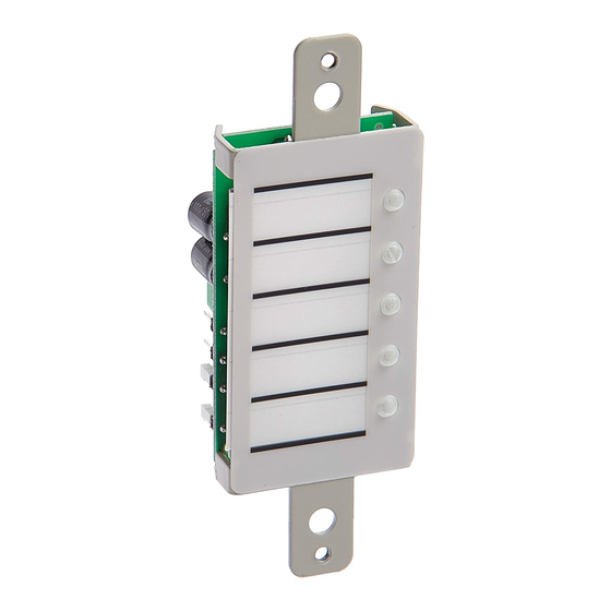
FSRZI-A(-SA) Remote Zone Indicators
Installation Sheet
Description
The FSRZI-A and FSRZI-SA are remote zone indicators for
F-series fire alarm control panels. The FSRZI-A provides five
red LEDs for indicating alarm zones. The FSRZI-SA provides
five bi-color LEDs (red for alarm zones; yellow for supervisory
and monitor zones). Configuration jumpers determine which
zones are indicated.
FSRZI-A and FSRZI-SA remote zone indicators include a
cover plate for installation in a standard, single-gang electrical
box. You can install one or two FSRZI-A and FSRZI-SA remote
zone indicators (with or without an FSRSI remote system
indicator) in an approved 2-, 3-, or 4-gang electrical box. Cover
plates for 2-, 3-, and 4-gang electrical boxes (model numbers
FSAT2, FSAT3, and FSAT4) are ordered separately.
A paper insert is provided for creating custom LED labels.
FSRZI-A and FSRZI-SA remote zone indicators are configured
using the jumpers described in the tables below.
Table 1: Group selection jumper
J5
Description
ON
Selects peripheral group 1
OFF
Selects peripheral group 2
Note:
Only two remote zone indicators are allowed per peripheral
group.
© 2013 UTC Fire & Security. All rights reserved.
Table 2: Zone selection jumpers
J4
J3
J2
ON
OFF
OFF
OFF
ON
OFF
OFF
OFF
ON
Note:
Install a jumper on J3 only when connected to a 10-zone control
panel.
Installation
Caution:
Make sure all power is disconnected from the panel
before installing. Observe static-sensitive handling practices.
For more information, refer to the technical reference manual
listed inside the control panel door.
To install the remote zone indicator:
1.
Configure the jumpers as described in Table 1 and
Table 2.
2.
Verify that all field wiring is free of opens, shorts, and
ground faults.
3.
Wire the remote zone indicator as shown Figure 1.
4.
Mount the remote zone indicator in the electrical box using
the two plain machine screws. See Figure 2.
Note:
If you are surface mounting the remote zone
indicator, you must install washers (provided) between it
and the surface mount box.
5.
Attach the faceplate to the remote zone indicator. Use the
two white machine screws provided with the faceplate.
Note:
Remote zone indicators will not operate properly until
detected by the control panel. For more information, see the
technical reference manual listed inside the control panel door.
1 / 2
Description
LEDs used to indicate zones 1 to 5
(IDC 1 to IDC 5 on the control panel)
LEDs used to indicate zones 6 to 10
(IDC 6 to IDC 10 on the control panel)
Not used
P/N 3101032 • REV 02 • REB 25JAN13
Advertisement

Related Manuals for Edwards FSRZI-A


Summary of Contents for Edwards FSRZI-A
- Page 1 Wire the remote zone indicator as shown Figure 1. box. You can install one or two FSRZI-A and FSRZI-SA remote zone indicators (with or without an FSRSI remote system Mount the remote zone indicator in the electrical box using indicator) in an approved 2-, 3-, or 4-gang electrical box.
- Page 2 24 VDC commons (−) wired together. Figure 2: Installing the remote zone indicator in a single-gang electrical box Compatible 1-gang electrical box FSRZI-A FSRZI-SA FSAT1 2 / 2 P/N 3101032 • REV 02 • REB 25JAN13...
Need help?
Do you have a question about the FSRZI-A and is the answer not in the manual?
Questions and answers