
Related Manuals for HALE Godiva KP1


Summary of Contents for HALE Godiva KP1
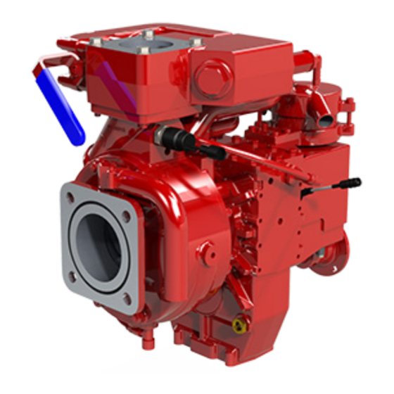
- Page 1 KP1 and KP2 Vehicle Mounted Fire Pump Installation and Operation Manual Publication: GP/311 Issue 5, February 2020...
-
Page 2: Amendment Record
Amendment Record Model: KP1_1510 / KP2_1510 Pump Modification No. Date Page/s Amendment New Issue Number January 2016 - May 2016 Add safety information on protecting moving parts during installation May 2016 5, 8 Add maximum allowable inlet pressure of 12 bar May 2016 5, 28 Add information on not running the... -
Page 3: Table Of Contents
CONTENTS Amendment Record Contents Introduction Safety Technical Data Installation Commissioning Operation Maintenance Fault Finding Operator Maintenance Log RTP - Round the Pump Foam System 38 Page 3 Godiva Ltd. policy is one of continuous development. We therefore reserve the right to amend specifications without notice or obligation. -
Page 4: Introduction
INTRODUCTION This publication provides information relating to the installation, commissioning and operation of the KP series pumps. It covers both the KP1 model - discharge of low pressure only and the KP2 model - simultaneous low and high pressure discharge. The KP series pump is designed for rear or midship mounting. The pump discharge rating is defined as - KP1_1510 is rated at 1500 l/min @ 10 Bar for low pressure. -
Page 5: Safety
SAFETY Please read this manual before operating the machinery. Safety notices - = non-compliance could affect safety IMPORTANT = in case of damage to pump ATTENTION = in case of personal hazards Installation and Commissioning Once packaging has been removed, installer should ensure rotating parts are not accessible. In operation Rotating parts must be guarded against accidental contact. - Page 6 Post-production Cleaning Fluid Immediately after production a special cleaning solution is used to clear the pump of any oil or grease that may be remaining inside the pump. Occasionally this cleaning solution leaves a deposit. This deposit has no effect on the performance and will be flushed away when the pump is first used. Cleaning fluid deposit –...
- Page 7 KP1_1510 and KP2_1510 Spares Spare parts for the KP pump are supplied in kit form for the various parts of the pump. Please refer to the KP Pump Spare Parts List. part number GP/317. Page 7 Godiva Ltd. policy is one of continuous development. We therefore reserve the right to amend specifications without notice or obligation.
-
Page 8: Technical Data
Technical Data Features unique to KP1 or KP2 model only are indicated, other parts are common Description Pump type KP1 Single stage - centrifugal Pump type KP2 Two stage. 1 stage centrifugal, 2 stage regenerative Shaft Stainless steel Seal Self-adjusting mechanical type Material Aluminium or bronze (applies to main castings) See Materials of Construction list for details... - Page 9 EN Designation (EN 1028:-1:2002) Godiva Description European Limit pressure Classification and specification standard pa lim bar Fire fighting centrifugal FPN 10 – 750 pump KP1_1510, low FPN 10-1000 EN 1028-1 pressure FPN 10-1500 FPN 15-1000 Fire fighting centrifugal FPN 10-750 / FPH 40-250 pump KP2_1510 - high FPN 10-1000 / FPH 40-250 EN 1028-1...
- Page 10 Figure 1. Cross Section of Prima KP1 Pump – Typical Priming valve Primer - reciprocating Discharge piston type Pump inlet Eccentric for driving Pump shaft piston primer Low pressure impeller Volute drain point Drive flange and shaft Mechanical seal Combined bearing housing and gearbox Page 10 Godiva Ltd.
- Page 11 Figure 2. Cross Section of Prima KP2 Pump – Typical High / Low pressure transfer chamber and filter Low pressure discharge high pressure discharge Primer - reciprocating piston type Pump inlet Eccentric for driving Pump shaft piston primer Low pressure impeller Volute drain point Drive shaft High pressure...
- Page 12 Essential installation data Fastening bolts, pump to chassis 8 off M8 x 1.25, Grade 8.8, Minimum 12mm cross-member Engagement. Torque to 14Nm Alignment of pump drive lines 7° Equivalent single joint angle - maximum Tank to suction pipework Ø 100mm Must incorporate a pliable element for flexibility.
-
Page 13: Installation
INSTALLATION 1. Before installation check the pump for any transit damage. 2. Mounting - Securing pump The pump is secured to the vehicle chassis by eight M8 bolts, the corresponding bolt holes on the pump will be located on the gearbox. Note: the gearbox can be supplied in three positions - left, right and down, so the location of the fixing holes will vary according to the gearbox position. - Page 14 4. Priming System Connect a flexible pipe (32mm, 1¼ inch internal dia.) to the discharge port on the side of the primer. The discharge options for the primer are - Discharge can be piped to the ground. Point discharge away from the operator. Discharge can be piped to a separate holding tank.
- Page 15 6. Pump Draining The volute and gearbox drain point must be connected to suitable drain taps. This photograph shows the pump drain and gearbox cooling circuit connected to a drain point at the front of the pump. Volute drain port - This connection is a G3/8 inch, for a tap or fitting to attach a...
- Page 16 8. Suction – Sideline Connection A tank to suction line can be accommodated if the special adaptor is fitted to the suction flange. The tank to pump line must incorporate a flexible coupling to allow for any movement. The adaptor can be rotated to suit different tank to suction line configurations. 9.
- Page 17 11. Pipework for Instrumentation and Safety Devices Vacuum and pressure gauge connection points are indicated in the pictures below. All connections and tubing must have a minimum working pressure rating of 19 bar. KP1 and KP2 models - low pressure gauge connection – on side of volute. Low pressure gauge connection, Rp ¼”...
- Page 18 Vacuum gauge connection – on suction tube Vacuum gauge connection, Rp ¼” Thermal Relief Valve (TRV) Elbow accepts 12mm (1/2 in) bore flexible hose DO NOT PLUG THIS VALVE. FEED DISCHARGE AWAY FROM OPERATOR. MAY BE FED INTO TANK IF FOAM IS NOT USED – available in two ratings, 42°C and 74°C. Note: TRV is shown on a KP2 model, located on high/low pressure...
- Page 19 Suction Pressure Relief Valve Pressure relief valve is fitted to relieve high pressure in hose reels when discharge nozzles are closed. The valve must discharge to atmosphere. Page 19 Godiva Ltd. policy is one of continuous development. We therefore reserve the right to amend specifications without notice or obligation.
- Page 20 General Arrangement Drawing - KP1, Part 1 369.5 189.8 Ø104.0 Ø180.0 Ø175.0 4x R8.5 OIL LEVEL SIGHT GLASS 160.0 91.0 98.0 PRESSURE GAUGE CONNECTION - Rp ¼ DIN 175 FLANGE PUMP 1410 DRIVE FLANGE DRAIN Rp 3/8 98.0 488.3 Page 20 Godiva Ltd.
- Page 21 General Arrangement Drawing - KP1, Part 2 279.8 OIL FILL 8 x M10 Ø145.0 SUCTION GAUGE CONNECTION - Rp ¼ Ø111.1 20.0 PRIMER DISCHARGE TO SUIT Ø32 HOSE Ø 78 98.0 172.3 TACHO DIRECTION OF DRIVE CONNECTION FLANGE ROTATION. CLOCKWISE DIRECTION SHOWN. COUNTER CLOCKWISE ALSO AVAILABLE 90.5...
- Page 22 General Arrangement Drawing - KP2, Part 1 HP OUTLET HP CROSSOVER HANDLE ARC OF OPERATION CONNECTION Rp 1¼ HIGH PRESSURE HIGH PRESSURE GAUGE CONNECTION FILTER Rp ¼ PRESSURE SWITCH OIL FILL Ø 104.0 Ø 175.0 Ø 180.0 4x R8.5 DIN175 / DN100 SUCTION FLANGE PUMP DRAIN...
- Page 23 General Arrangement Drawing - KP2, Part 2 HIGH PRESSURE HP OUTLET CONNECTION GAUGE CONNECTION Rp 1¼ 364.6 Rp ¼ 265.6 SUCTION PRESSURE GAUGE CONNECTION - Rp ¼ 8 x M10 PRIMER DISCHARGE TO SUIT Ø32 HOSE Ø145.0 Ø111.1 TACHO LOW PRESSURE CONNECTION OUTLET Ø...
- Page 24 Priming Wiring Page 24 Godiva Ltd. policy is one of continuous development. We therefore reserve the right to amend specifications without notice or obligation.
- Page 25 Tachometer sender unit wiring Page 25 Godiva Ltd. policy is one of continuous development. We therefore reserve the right to amend specifications without notice or obligation.
- Page 26 Priming - Harness Wiring Schematic PRESSURE TACHO SWITCH GAUGE CONNECTION CONNECTION ITT CANON ITT CANON SURE SURE -SEAL -SEAL TACHO SENSOR CONNECTION SPEED ITT CANON SWITCH SURE CONNECTION -SEAL ITT CANON SURE -SEAL CLUTCH CONNECTION ITT CANON SURE -SEAL PRESSURE SWITCH TACHO GAUGE SPEED SWITCH TACHO SENSOR...
-
Page 27: Commissioning
COMMISSIONING Check all mountings are secure. Check all pipework has been connected. Check engine rotation against PTO rotation. Ensure drive is connected. Ensure water is available and connected Ensure power is available and connected. Preparation for use Fill the bearing housing with the specified grade and quantity of oil (see Technical Data). Check oil level only when vehicle is stationary and level. -
Page 28: Operation
OPERATION Do not use the pump in explosive environments. Do not use the pump without the inlet screen fitted. Do not run the pump without water for more than one minute, as dry running will damage the seal. The Godiva KP pump is designed for extinguishing fires with an unrestricted water source. Water must be as clean as possible and can be fresh water or sea water. - Page 29 IMPORTANT Do not operate the pump for extended periods with the discharge valves closed. This may cause the pump to overheat. On KP2 pumps a thermal relief valve is fitted as standard to help prevent overheating. Operation – from a pressurised source, e.g. hydrant or vehicle tank If water is supplied from a pressurised source then priming is not necessary.
- Page 30 When not required the high/low pressure selector lever should be left in the low pressure position (down). This will minimise pump power demand, consume less fuel and produce less emissions and noise. Shutdown Return the pump to idling speed before disengaging the pump drive. Drain the pump of any water by opening the drain tap at the bottom of the mounting platform (or at the bottom of the volute if no platform is fitted).
-
Page 31: Maintenance
MAINTENANCE Maintenance intervals and action required Interval Action required Items Required After each use – Flush pump through with clean Supply of clean water water and drain volute Delivery Valves Check the valves open and close If the valve is stiff, report (applies primarily to UK screw down type) freely. - Page 32 MAINTENANCE - CONTINUED Maintenance intervals and action required Interval Action required Items Required Every 1 year - Change oil in gearbox housing - if Drain oil from housing and refill with EP80 or 90 gear oil. 1.1 EP80/90 oil used. new oil litre Every 2 years -...
- Page 33 Vacuum Test Place the blanking cap(s) in position on the inlet(s) of the pump and close the delivery valves. Run the pump at 1300-1500 rpm and observe the vacuum/compound needle. When a vacuum of 0.81bar is obtained, stop the pump. This vacuum should be maintained for at least 15 seconds or drop no more than 0.07bar in a minute.
-
Page 34: Fault Finding
FAULT FINDING The following conditions may occur – Loss of suction 1 Suction is lost Are all suction connections airtight? Conduct pump pressure and Tighten all vacuum tests connections Trace leaks, rectify and retest pumps Suction is restored Page 34 Godiva Ltd. - Page 35 Loss of suction 2 - Suction is lost Reduce suction Is suction lift too deep? lift Air leaks in system? Conduct pump pressure and vacuum tests Trace leaks, rectify and retest pumps Suction is restored Page 35 Godiva Ltd. policy is one of continuous development. We therefore reserve the right to amend specifications without notice or obligation.
- Page 36 Cavitation – Pump makes excessive rattling noise during operation Probably due to pump cavitating? Decrease pump speed Continue with Has noise disappeared? pump use Investigate further - possible mechanical problem Page 36 Godiva Ltd. policy is one of continuous development. We therefore reserve the right to amend specifications without notice or obligation.
-
Page 37: Operator Maintenance Log
OPERATOR MAINTENANCE LOG Pump serial number ..... Use this log to record faults, part replacements and major overhauls. Please contact Customer Service at Godiva Ltd. prior to any proposed return of either a single part, or a complete assembly. -
Page 38: Rtp - Round The Pump Foam System
RTP - ROUND THE PUMP FOAM SYSTEM Introduction The Godiva KP Series range of pumps can be fitted with a Round the Pump foam system (RTP) capable of inducing up to 120 litres per minute of foam compound into the pump. The system is compact, self-contained and is mounted on the pump suction tube and volute. - Page 39 Installation The RTP foam system is compact, but the builder of the fire appliance must mount the foam induction unit close to the pump. Tubing must be connected from the pump discharge manifold to the driving water valve, then to the foam induction unit, and then to the pump suction Foam compound can be supplied to the inductor from a free-standing tank or a vehicle-mounted tank.
- Page 40 Insert hose fittings where indicted in the diagram above. Connect the components together with the tubing size indicated. Note the specifications of the adaptor/connector threads. Water supply to foam inductor - Ø19mm hose, capable of .9 vacuum, 21 Bar Pressure Foam/water Discharge Rp ¾...
- Page 41 Operation The RTP foam system is suitable for use when the pump is being supplied with water from – Vehicle mounted tank Free standing tank or open water Pressure fed source The system is very simple to operate. First check the amount of water flow discharging through the branch nozzles in use. For best results this should be at the maximum possible flow rate for the nozzles, typically 230 or 475l/min of water.
- Page 42 When the pump is operated with a pressurised (boosted) suction, the pump pressure must be increased to ensure satisfactory foam induction. A ratio between delivery pressure and suction pressure must be maintained as tabulated below. Pump pressure Driving ratio = ------------------------- Suction pressure RTP Flow rate l/min...
- Page 43 Godiva Ltd Tel +44 (0)1926 623600 A Unit of IDEX Corporation Fax +44 (0)1926 623666 Charles St www.godiva.co.uk Warwick CV34 5LR godiva@idexcorp.com England Page 43 Godiva Ltd. policy is one of continuous development. We therefore reserve the right to amend specifications without notice or obligation.
Need help?
Do you have a question about the Godiva KP1 and is the answer not in the manual?
Questions and answers