Table of Contents
Advertisement
6/1/99
ROTARY GEAR PUMP
PROPORTIONING SYSTEM
DESCRIPTION, INSTALLATION AND
NOTICE: This manual is divided into four sections for clarity and ease of use. Section I: DESCRIPTION; Provides an
introduction to the Hale Foammaster System along with guidelines for designing and ordering a complete system.
Section II: INSTALLATION; Provides information to assist the OEM with installation and initial set-up of Hale FoamMaster
systems on an apparatus. Section III: SET-UP AND CALIBRATION; Is used by the installer and end user for start-up and
calibration of the Hale FoamMaster system. Section IV: OPERATION; Is primarily used by the apparatus user for proper
operation and maintenance of the Hale FoamMaster system. Each manual section can be a stand alone section or
can be used in conjunction with each other.
Hale FoamMaster System Serial Number: ____________________________
All Hale products are quality components: ruggedly designed, accurately machined, precision inspected, carefully assembled
and thoroughly tested. In order to maintain the high quality of your unit, and to keep it in a ready condition, it is important to
follow the instructions on care and operation. Proper use and good preventive maintenance will lengthen the life of your unit.
ALWAYS INCLUDE THE UNIT SERIAL NUMBER IN CORRESPONDENCE.
HALE PRODUCTS, INC. l A Unit of IDEX Corporation l 700 Spring Mill Avenue l Conshohocken, PA 19428 l TEL: 610-825-6300 l FAX: 610-825-6440
MANUAL P/N 029-0020-35-0, REV E, © 1999 HALE PRODUCTS, INC., PRINTED IN U.S.A.
ELECTRONIC FOAM
OPERATION
MANUAL
Hale Products cannot assume responsibility for product failure resulting from improper
maintenance or operation. Hale Products is responsible only to the limits stated in the product
warranty. Product specifications contained in this material are subject to change without notice.
Advertisement
Table of Contents

Subscribe to Our Youtube Channel
Related Manuals for HALE FOAM MASTER 3.3


Summary of Contents for HALE FOAM MASTER 3.3
- Page 1 ALWAYS INCLUDE THE UNIT SERIAL NUMBER IN CORRESPONDENCE. HALE PRODUCTS, INC. l A Unit of IDEX Corporation l 700 Spring Mill Avenue l Conshohocken, PA 19428 l TEL: 610-825-6300 l FAX: 610-825-6440 MANUAL P/N 029-0020-35-0, REV E, © 1999 HALE PRODUCTS, INC., PRINTED IN U.S.A.
-
Page 2: Table Of Contents
PARTS IDENTIFICATION ...................... IV-22 WARRANTY ......................... IV-29 System installer must provide two copies of this Hale FoamMaster System Description, Installation and Operation Manual to the end user of the equipment. If additional manuals are required, contact Hale Products Inc. Communications Department at (610) 825-6300. -
Page 3: Section I: Description
HALE PRODUCTS, INC. l A Unit of IDEX Corporation l 700 Spring Mill Avenue l Conshohocken, PA 19428 l TEL: 610-825-6300 l FAX: 610-825-6440 Hale Products cannot assume responsibility for product failure resulting from improper maintenance or operation. -
Page 4: Safety
ELECTRONIC FOAM PROPORTIONING SYSTEM SAFETY Hale FoamMaster systems are designed to provide reliable and safe foam concentrate injection. Before installing or operating a Hale FoamMaster system read all safety precautions and follow carefully to ensure proper installation and personnel safety. - Page 5 When control unit, foam discharge multiplexing installing the in-line strainer in systems equipped with Hale MDT ΙΙ or Hale MST display unit) will void warranty. 12. Use mounting hardware that is make sure the in-line strainer/valve...
-
Page 6: System Description
The control unit, mounted on the operator constant regardless of changes in system panel, is the single control point for the Hale pressure or the number of discharges open. FoamMaster system. Depressing the ON button starts foam concentrate injection. - Page 7 The available Air Dual Tank (ADT) valve for concentrate tank. The standard in-line the Hale FoamMaster system is an air strainer/valve assembly has a composite operated foam tank selector valve that non-metallic housing with stainless steel provides selection of foam concentrate mesh strainer element.
- Page 8 ROTARY GEAR PUMP ELECTRONIC FOAM PROPORTIONING SYSTEM All Hale FoamMaster systems require at least cable length,16.5 feet or 6.5 feet). one flowsensor for operation. Some systems 3. Determine tank selector desired based may be designed to operate using multiple on the number of foam concentrate tanks installed (ADT or MDT ΙΙ...
-
Page 9: Hale Foammaster System Specifications
¾ INCH NPT SUCTION HOSE CONNECTION 2.58 IN. (66 MM) ½ INCH NPT BYPASS HOSE CONNECTION Hale FoamMaster Installation Envelope Dimensions Configured for use with MDT ΙΙ, MST or No Tank Selector Option Section Ι Ι Ι Ι Ι : Description Ι−6... - Page 10 1 INCH I.D. HOSE (94 MM) TANK A CONNECTION ¾ INCH I.D. HOSE 4.76 IN. (121 MM) FLUSH WATER CONNECTION ½ INCH NPT Hale FoamMaster Installation Envelope Dimensions Configured with Optional ADT Section Ι Ι Ι Ι Ι : Description Ι-7...
-
Page 11: System Configuration
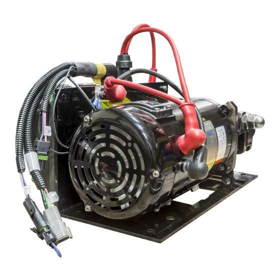
SYSTEM CONFIGURATION Hale FoamMaster System Model (Model 3.0, Model 3.3 or Model 5.0) All Hale FoamMaster sytems include: Foam Pump/Motor Assembly, Control Unit, Control Cable and Check Valve/Injector Fitting Foam Pump/Motor Assembly (Shown with Bypass Valve when configured for MDT ΙΙ, MST or no tank selector option) 6-Pin Control Cable 16.5 Feet (Recommended) (P/N 013-2020-05-0) - Page 12 ROTARY GEAR PUMP ELECTRONIC FOAM PROPORTIONING SYSTEM Dual Foam Concentrate Tank System Options Panel Switch/Indicator Light Placard Assembly Optional Color Coded Air Connection Harness (P/N 507-0380-00-0) Foam Pump/Motor Assembly with Air Dual Tank (ADT) Selector (P/N 538-1640-02-0) Manual Dual Tank (MDT ΙΙ) Selector and Wiring Harness (P/N 538-1490-11-0) MDT ΙΙ...
- Page 13 (1 Inch NPT Threads. Use With Class A and thin Class B Foam Concentrates) and Class B Foam Concentrates) Hale FS Series Strainers (Use When Strainer is Subjected to Flushing Water Pressure) Section Ι Ι Ι Ι Ι : Description...
- Page 14 ROTARY GEAR PUMP ELECTRONIC FOAM PROPORTIONING SYSTEM Low Tank Level Sensor Options (One Low Tank Level Sensor is Required for Each Foam Tank) Side Mount Low Tank Level Sensor (P/N 200-2110-02-0) (½ Inch NPT Threaded Bushing to Mount From Outside Foam Tank) Brass Bottom Mount Low Tank Level Sensor (P/N 200-2110-04-0)
- Page 15 ELECTRONIC FOAM PROPORTIONING SYSTEM Flowsensors Each Hale Foammaster System Requires at Least One Flowsensor to Operate. Flowsensors must be Selected Based on the Minimum and Maximum Water Flow in the Foam Capable Discharge. Following is a List of HPF Flowsensor Models, Pipe Size and Rated Flow...
- Page 16 ROTARY GEAR PUMP ELECTRONIC FOAM PROPORTIONING SYSTEM Flowsensor Installation Dimensions Minimum of 4 inches (102 mm) required above flowsensor tee for sensor removal and service. Section Ι Ι Ι Ι Ι : Description Ι-13...
- Page 17 ROTARY GEAR PUMP ELECTRONIC FOAM PROPORTIONING SYSTEM Foam Discharge Multiplexing Display Unit Foam Discharge Multiplexing Display Unit (Including Pressure Transducer) (P/N 200-2550-00-0) (Required Component When Number of Flowsensors is Greater Than One) (When Multiplexing Units are Installed a FoamMaster Power Filter Kit (P/N 546-1870-00-0) Must be Installed) 6-Pin Pressure Transducer Cable 16.5 Feet (Recommended) (P/N 013-2020-05-0)
- Page 18 ROTARY GEAR PUMP ELECTRONIC FOAM PROPORTIONING SYSTEM Additional Components 2433D FLANGE OUTLET CONNECTIONS 3 INCH NPT or 4 INCH OUTLET VICTAULIC INLET CONNECTION OUTLET INLET 115 FLANGE FOAM OUTLET CONNECTIONS INJECTION FOAM (EACH SIDE) INJECTION DRAIN CONNECTION Maxi Manifold Mini Manifold (P/N 178-0420-00-0) (P/N 178-0320-02-0) 3 Inch "115"...
- Page 19 ROTARY GEAR PUMP ELECTRONIC FOAM PROPORTIONING SYSTEM Additional Components 2433D (P/N 046-0050-00-0) (P/N 046-0040-00-0) Flange Gaskets Close Fit Flanged Elbow Close Fit Flanged Elbow (P/N 098-0140-00-0) (P/N 098-0190-00-0) 115 flange inlet with 3 inch Victaulic outlet. 2433D flange inlet with 3 inch female NPT and 4 inch Victaulic outlet.
- Page 20 HOSE CHECK VALVE DISTRIBUTION INJECTOR FITTING HALE FOAMMASTER WATERWAY WATERWAY FOAM SOLUTION FLOWSENSOR CHECK CHECK DISCHARGE(S) VALVE VALVE FIRE PUMP Figure 1-1. Hale FoamMaster System Layout with Single Foam Concentrate Tank Section Ι Ι Ι Ι Ι : Description Ι-17...
- Page 21 CORDSET HALE WATERWAY FOAMMASTER CHECK WATERWAY VALVE FLOWSENSOR FOAM SOLUTION CHECK DISCHARGE(S) VALVE FIRE PUMP Figure 1-2. Hale FoamMaster System Layout with Single Foam Concentrate Tank, MST and In-line Strainer/Valve Assembly Section Ι Ι Ι Ι Ι : Description Ι−18...
- Page 22 CORDSET HALE WATERWAY FOAMMASTER CHECK WATERWAY FOAM SOLUTION VALVE CHECK FLOWSENSOR DISCHARGE(S) VALVE FIRE PUMP Figure 1-3. Hale FoamMaster System Layout with Single Foam Concentrate Tank, MST and FS Series Strainer Section Ι Ι Ι Ι Ι : Description Ι-19...
- Page 23 HALE WATERWAY FOAMMASTER CHECK VALVE WATERWAY FLOWSENSOR FOAM SOLUTION CHECK DISCHARGE(S) VALVE FIRE PUMP Figure 1-4. Hale FoamMaster System Layout with Dual Foam Concentrate Tanks, MDT ΙΙ and In-line Strainer/Valve Assembly Section Ι Ι Ι Ι Ι : Description Ι−20...
- Page 24 HALE CHECK WATERWAY FOAMMASTER FOAM SOLUTION VALVE CHECK DISCHARGE(S) VALVE FLOWSENSOR FIRE PUMP Figure 1-5. Hale FoamMaster System Layout with Dual Foam Concentrate Tanks, MDT ΙΙ and FS Series Strainer Assembly Section Ι Ι Ι Ι Ι : Description Ι-21...
- Page 25 INJECTOR FITTING HALE FOAMMASTER WATERWAY FOAM SOLUTION WATERWAY CHECK DISCHARGE(S) FLOWSENSOR CHECK VALVE FIRE VALVE PUMP Figure 1-6. Hale FoamMaster System Layout with Dual Foam Concentrate Tanks, ADT and In-line Strainer/Valve Assemblies Section Ι Ι Ι Ι Ι : Description Ι−22...
- Page 26 HALE WATERWAY FOAMMASTER CHECK WATERWAY FOAM SOLUTION VALVE CHECK FLOWSENSOR DISCHARGE(S) VALVE FIRE PUMP Figure 1-7. Hale FoamMaster System Layout with Dual Foam Concentrate Tanks, ADT and FS Series Strainer Assemblies Section Ι Ι Ι Ι Ι : Description Ι-23...
-
Page 27: Section Ii: Installation
HALE PRODUCTS, INC. l A Unit of IDEX Corporation l 700 Spring Mill Avenue l Conshohocken, PA 19428 l TEL: 610-825-6300 l FAX: 610-825-6440 Hale Products cannot assume responsibility for product failure resulting from improper maintenance or operation. -
Page 28: Safety
ELECTRONIC FOAM PROPORTIONING SYSTEM SAFETY Hale FoamMaster systems are designed to provide reliable and safe foam concentrate injection. Before installing or operating a Hale FoamMaster system read all safety precautions and follow carefully to ensure proper installation and personnel safety. - Page 29 When control unit, foam discharge multiplexing installing the in-line strainer in systems equipped with Hale MDT ΙΙ or Hale MST display unit) will void warranty. 12. Use mounting hardware that is make sure the in-line strainer/valve...
-
Page 30: Apparatus Installation Planning
Differences in apparatus plumbing and FS15 or FS25 panel mounted foam foam system configuration make it strainer impractical to show exactly how each Hale ADT operating switch and indicator lights FoamMaster system is installed on a (ADT valve is integral part of foam particular apparatus. - Page 31 Hale concentrate hose to prevent spillage during MDT ΙΙ or Hale MST make sure the in-line service. An MST or MDT ΙΙ can serve this strainer/valve assembly is in the hose on purpose also.
-
Page 32: Installer Supplied Component Recommendations
Due to the many differences in apparatus RECOMMENDED COMPONENTS: configuration and apparatus design Hose: PVC, Kuriyama Kuri-Tec K7130 requirements the Hale FoamMaster system series installer must supply components such as Fittings: Hose Barb Type; Brass, Stainless mounting brackets, piping, hoses, fittings Steel or Nylon and some electrical wiring. - Page 33 Fittings: Brass or Stainless Steel working pressure. The foam concentrate bypass hose should Hale 3 inch "115" flange type check valves be long enough to extend past the (Hale P/N 038-1570-00-0) can be used for apparatus running board making foam most installations on pumps with "115"...
- Page 34 Hale FoamMaster system. When the Hale ADT, Hale FoamMaster MDT ΙΙ or Hale MST is installed a check valve is Primary power must be supplied from the provided integral to the flushing water line...
- Page 35 If the ground strap length exceeds 18 components must not be supplied from this inches (457 mm), a wider ground strap wire. DO NOT connect the primer and Hale should be used or use a double thickness of FoamMaster to the same power wire.
-
Page 36: Foam Pump Mounting
INCORRECT vibration and stresses of apparatus operation. Figures 2-2 and 2-3 provide the mounting envelope dimensions for the Hale FoamMaster foam pump and motor assembly. Position the foam pump so the ON/OFF switch and bypass valve are easily accessible. - Page 37 9.43 IN. (240 MM) ½ INCH NPT INJECT HOSE CONNECTION ¾ INCH NPT SUCTION HOSE CONNECTION 2.58 IN. (66 MM) ½ INCH NPT BYPASS HOSE CONNECTION Figure 2-2. Hale FoamMaster Installation Envelope Dimensions Section ΙΙ ΙΙ ΙΙ ΙΙ ΙΙ: Installation ΙΙ-10...
- Page 38 DIA. THRU HOLE 14.06 IN. 0.75 IN. (4 PLACES) (357 MM) (19 MM) 15.56 IN. (395 MM) Figure 2-4. Hale FoamMaster Foam Pump and Motor Assembly Base Plate Dimensions and Mounting Hole Locations Section ΙΙ ΙΙ ΙΙ ΙΙ ΙΙ: Installation ΙΙ-11...
-
Page 39: Plumbing Component Installation
ELECTRONIC FOAM PROPORTIONING SYSTEM PLUMBING COMPONENT INSTALLATION Hale FoamMaster System plumbing diagrams are located at the end of this manual section. The diagrams provide recommended guidelines for the installation of system components that handle water, foam concentrate and foam solution. The sequence in which the plumbing installation is completed depends on the individual installation. - Page 40 Some applications will require installation of ensure that pump and tank water remain a Hale mini or maxi manifold to provide a uncontaminated. common foam concentrate injection point and the use of multiple flowsensors with...
- Page 41 3 inch to 2-½ inch, 2-½ inch to 2 inch or 2 As an alternative to using reduced pipe inch to 1-½ inch) to provide for better size, Hale HPF flowsensor tees are machined accuracy at low flow rates. Always refer to with a ring that accepts Victaulic type the flowsensor selection chart in Section Ι...
- Page 42 Do not mount a flowsensor directly CORRECT after an elbow or valve. Valves create severe turbulence when they are “gated”. With the use of Hale foam discharge AT LEAST 5X THE PIPE multiplexing display units, 2 to 8 flowsensors VALVE OR WATER...
- Page 43 Flush water thread connections on the ADT are ½ inch CAUTION: The Hale HPF flowsensor is NPT and on the Hale MDT ΙΙ and Hale MST assembled and tested at the factory. they are ¼ inch NPT. The system installer...
- Page 44 When installing the in-line 1. Choose a location on the apparatus strainer in systems equipped with Hale MDT ΙΙ or Hale MST make sure the in-line strainer/valve assembly is in the hose on STRAINER BRACKET OUTLINE the inlet side of the valve. If the strainer...
- Page 45 5. Install the clear plastic hose from the in- line strainer/valve assembly outlet to the inlet of the Hale MDT ΙΙ, Hale MST or 2. Refer to the diagram in figure 2-13 and mark 4 holes for mounting the foam foam concentrate pump.
- Page 46 ROTARY GEAR PUMP ELECTRONIC FOAM PROPORTIONING SYSTEM 3.00 IN. 1.00 IN. 1.50 IN. 2.13 IN. (54 MM) (76 MM) 0.34 IN. (9 MM) (38 MM) (25 MM) DIA. HOLE DIA. THRU HOLE 1.00 IN. (4 PLACES) (25 MM) 3.38 IN. (86 MM) DIA.
- Page 47 Figure 2-16. Check Valve/Injector Fitting Position 7. Install the hose from the strainer outlet to the inlet of the Hale FoamMaster foam pump or selector valve. The check valve/injector fitting has 1 inch NPT threads on the outside to fit into the 1...
- Page 48 A bypass port is provided on the discharge the INJECT port (see figure 2-19) and which side of the Hale ADT or a bypass valve is port is the BYPASS port. The INJECT port is mounted on the discharge of the foam identified on the bypass valve placard.
- Page 49 ROTARY GEAR PUMP ELECTRONIC FOAM PROPORTIONING SYSTEM each of the other ports. The bypass port on ADT AIR CONNECTIONS the ADT is identified by a label above the If the ADT option is used, install the port. operating switch and indicator light placard for the ADT on the apparatus operator Bypass hose connections are ½...
- Page 50 ROTARY GEAR PUMP ELECTRONIC FOAM PROPORTIONING SYSTEM 1.69 IN. (43 mm) PLACARD OUTLINE SHOWN 1.25 IN. FOR REFERENCE ONLY (32 mm) DRILL 4 THRU HOLES 7/32 IN. (6 mm) DIA. 0.84 IN. (21 mm) 3.50 IN. (89 mm) 2.75 IN. (70 mm) 0.25 IN.
- Page 51 ROTARY GEAR PUMP ELECTRONIC FOAM PROPORTIONING SYSTEM AIR OUT A (GREEN) TANK A AIR IN INDICATOR (BLACK) SELECTOR SWITCH TANK B ELECTRICAL HARNESS INDICATOR AIR OUT B (RED) ADT PANEL PLACARD SIDE VIEW PANEL PLACARD ASSEMBLY ¼ INCH O.D. AIR HOSE OR AIR HARNESS ASSEMBLY...
-
Page 52: System Plumbing Diagrams
Due to variations in apparatus configuration and individual component locations, lengths of hoses and piping is not provided. The material described and component sizes are those which will provide optimum performance of a Hale FoamMaster system. These diagrams are intended as guidelines to assist the system installer with selection of hoses and fittings along with the connections required. - Page 53 OUTSIDE DIAMETER RATED AT HOSE 500 PSI (34 BAR) FIRE PUMP HALE FOAM SOLUTION FOAMMASTER WATERWAY WATERWAY DISCHARGE(S) CHECK CHECK FLOWSENSOR VALVE VALVE Hale FoamMaster System Plumbing Diagram with Single Foam Concentrate Tank Section ΙΙ ΙΙ ΙΙ ΙΙ ΙΙ: Installation ΙΙ-26...
- Page 54 AT 500 PSI (34 BAR) FIRE PUMP HALE WATERWAY FOAMMASTER CHECK WATERWAY VALVE FOAM SOLUTION FLOWSENSOR CHECK DISCHARGE(S) VALVE Hale FoamMaster System Plumbing Diagram with Single Foam Concentrate Tank, MST and In-line Strainer/Valve Assembly Section ΙΙ ΙΙ ΙΙ ΙΙ ΙΙ: Installation ΙΙ-27...
- Page 55 AT 500 PSI (34 BAR) HOSE FIRE PUMP HALE WATERWAY FOAMMASTER WATERWAY CHECK FOAM SOLUTION CHECK VALVE FLOWSENSOR DISCHARGE(S) VALVE Hale FoamMaster System Plumbing Diagram with Single Foam Concentrate Tank, MST and FS Series Strainer Section ΙΙ ΙΙ ΙΙ ΙΙ ΙΙ: Installation ΙΙ-28...
- Page 56 AT 500 PSI (34 BAR) FIRE PUMP HALE WATERWAY FOAMMASTER CHECK WATERWAY VALVE FLOWSENSOR CHECK FOAM SOLUTION VALVE DISCHARGE(S) Hale FoamMaster System Plumbing Diagram with Dual Foam Concentrate Tanks, MDT ΙΙ and In-line Strainer/Valve Assembly Section ΙΙ ΙΙ ΙΙ ΙΙ ΙΙ: Installation ΙΙ-29...
- Page 57 INCH INSIDE DIAMETER FIRE PUMP HALE WATERWAY FOAMMASTER CHECK FOAM SOLUTION WATERWAY VALVE CHECK DISCHARGE(S) FLOWSENSOR VALVE Hale FoamMaster System Plumbing Diagram with Dual Foam Concentrate Tanks, MDT ΙΙ and FS Series Strainer Assembly Section ΙΙ ΙΙ ΙΙ ΙΙ ΙΙ: Installation ΙΙ-30...
- Page 58 INCH INSIDE DIAMETER CONNECTION FITTING FIRE PUMP HALE WATERWAY FOAMMASTER FOAM SOLUTION CHECK DISCHARGE(S) WATERWAY VALVE FLOWSENSOR CHECK VALVE Hale FoamMaster System Plumbing Diagram with Dual Foam Concentrate Tanks, ADT and In-line Strainer/Valve Assemblies Section ΙΙ ΙΙ ΙΙ ΙΙ ΙΙ: Installation ΙΙ-31...
- Page 59 INCH INSIDE DIAMETER FIRE PUMP HALE WATERWAY FOAMMASTER CHECK WATERWAY VALVE CHECK FOAM SOLUTION FLOWSENSOR VALVE DISCHARGE(S) Hale FoamMaster System Plumbing Diagram with Dual Foam Concentrate Tanks, ADT and FS Series Strainer Assemblies Section ΙΙ ΙΙ ΙΙ ΙΙ ΙΙ: Installation ΙΙ-32...
-
Page 60: Electrical Installation
The resulting in possible system failure. Hale FoamMaster system is designed to be installed with a minimum of electrical • The cables shipped with each Hale connections. Complete electrically... - Page 61 For stainless steel a FoamMaster power filter kit (Hale P/N and vinyl coated panels a ground strap 546-1870-00-0) on the Hale FoamMaster ½ inch (12 mm) wide must be attached foam pump.
- Page 62 ELECTRONIC FOAM PROPORTIONING SYSTEM ACCESSORY CONNECTOR (Plug inserted at factory when single tank installed.) (Connection made at factory when Hale MDT ΙΙ ΙΙ ΙΙ ΙΙ ΙΙ or Hale ADT option installed.) (Field connection required at installation when Hale MST option installed.) CONTROL UNIT...
- Page 63 FLOWSENSOR TRANSDUCER SHUTOFF VALVE FOAM SOLUTION DISCHARGE Figure 2-26. Multiple Flowsensor Connections with Hale Foam Discharge Multiplexing Display Units inch NPT bushing and a bulkhead fitting TOP MOUNT LOW LEVEL SENSOR with 1 inch FNPT threads (see figure 2-28). OPTION The center of the switch must be located at least 1-½...
- Page 64 ROTARY GEAR PUMP ELECTRONIC FOAM PROPORTIONING SYSTEM foam pump/motor assembly. Be sure not to remove the float from the shaft on the low tank level sensor assembly. If the FLOAT POSITION float is installed in the reverse position, (SUFFICIENT FOAM CONCENTRATE IN TANK) “...
- Page 65 ROTARY GEAR PUMP ELECTRONIC FOAM PROPORTIONING SYSTEM 1.44 in. (37 mm) STRAIN STRAIN RELIEF RELIEF 0.72 in. GLAND NUT SENSOR FLANGE AND (18 mm) WIRE GASKET FNPT X TUBE FITTING 1.44 in. (37 mm) 0.72 in. (18 mm) 1.31 in. (33 mm) INCH O.D.
- Page 66 ¼ inch lockwashers. DUAL FOAM TANK SYSTEM When the Hale FoamMaster system is installed using a Hale ADT or Hale MDT ΙΙ e. Make final adjustment to the sensor position by pulling the tubing sections up connect the low tank level sensors using the through the flange until sensor is 1-½...
- Page 67 A stud labeled NEG (—) is located on the distribution box to A-B SWITCHBOX MOUNTED ON attach the chassis ground strap to the Hale FOAM PUMP FoamMaster system. (See figure 2-24) Figure 2-31. Low Tank Sensor A-B...
- Page 68 Proper installation of system components flat bundle instead of making a round coil. and cables along with proper grounding will (See Figure 2-32) limit radio interference caused by the Hale FoamMaster system. Additionally, make REMOTE ACTIVATION SWITCH sure radio cables and hardware are not...
- Page 69 ROTARY GEAR PUMP ELECTRONIC FOAM PROPORTIONING SYSTEM 4. Connect the remote activation switch cable from the connector on the control unit (see figure 2-25) to the connector on the back of the remote activation switch. FOUR 0.203 IN. 2.50 IN. (5 MM) THRU 3.22 IN.
-
Page 70: Hale Foammaster System Electrical Diagrams
MAXIMUM 18 INCHES (457 mm) LONG BATTERY CABLE FOR CABLE LENGTH UP TO 6 FEET. FOR CABLE LENGTH OVER 6 FEET REFER TO TABLE 2-2 FOR PROPER GAUGE WIRE. HALE FOAMMASTER SYSTEM (NO TANK OPTION) CONTROL CONTROL LOW TANK LEVEL SENSORS... - Page 71 USE 1-¼ INCH WIDE FLAT BRAIDED GROUND STRAP FOR CABLE LENGTH OVER 6 FEET REFER TO TABLE MAXIMUM 18 INCHES (457 mm) LONG 2-2 FOR PROPER GAUGE WIRE. HALE FOAMMASTER SYSTEM WITH MDT ΙΙ LOW TANK LEVEL SENSORS CONTROL USE MINIMUM 16 AWG TYPE...
-
Page 72: Start-Up Checklist
Splices in wires sealed from moisture using adhesive filled heat shrink tubing. q Hale FoamMaster system ON/OFF switch on the distribution box is in the ON position. q If installed, ADT, MST or MDT ΙΙ electrical connections correct. -
Page 73: System Installer Start-Up
ROTARY GEAR PUMP ELECTRONIC FOAM PROPORTIONING SYSTEM SYSTEM INSTALLER START-UP When energizing the Hale FoamMaster system at the system installer facility for the first time the following procedures shall be used. INITIAL SYSTEM POWER CHECK Observe the display on the control unit... - Page 74 "0" on the control unit display. Once until the LED under TOTAL FOAM lights. proper operation is verified place the Depress ON button to energize Hale selector to TANK A position (or FOAM FoamMaster system. Observe the TANK position on MST).
- Page 75 11. Verify operation of and calibrate flowsensor(s) as required using flowsensor calibration procedures in the user calibration section. This completes the Hale FoamMaster system operation checks that can be accomplished at the system installer facility. Foam pump feedback calibration along...
-
Page 76: Section Iii: Set-Up And Calibration
HALE PRODUCTS, INC. l A Unit of IDEX Corporation l 700 Spring Mill Avenue l Conshohocken, PA 19428 l TEL: 610-825-6300 l FAX: 610-825-6440 Hale Products cannot assume responsibility for product failure resulting from improper maintenance or operation. -
Page 77: Safety
ELECTRONIC FOAM PROPORTIONING SYSTEM SAFETY Hale FoamMaster systems are designed to provide reliable and safe foam concentrate injection. Before installing or operating a Hale FoamMaster system read all safety precautions and follow carefully to ensure proper installation and personnel safety. - Page 78 When control unit, foam discharge multiplexing installing the in-line strainer in systems equipped with Hale MDT ΙΙ or Hale MST display unit) will void warranty. 12. Use mounting hardware that is make sure the in-line strainer/valve...
-
Page 79: Installation And Delivery Checklist
ELECTRONIC FOAM PROPORTIONING SYSTEM INSTALLATION AND DELIVERY CHECKLIST After the Hale FoamMaster system has been installed the following check list should be used to verify installation and ensure proper system set-up when apparatus is delivered to the end user. Use procedures in referenced manual sections. -
Page 80: Initial End User Set-Up
— FLOW, TOTAL FLOW, % FOAM, TOTAL FOAM, ON and all bargraph LEDs will light along with "88888" for several seconds. "HALE" will then appear for INITIAL POWER-UP several seconds while the system checks itself followed by the default display (See figure 3-1). - Page 81 150 GPM). Display will show “S” at the left most position to indicate the simulated flow (See figure 3-2). 4. Engage the Hale FoamMaster system by pressing the red ON button. The ON button will illuminate to indicate the system is on and the bargraph indicates whether foam concentrate is being pumped.
-
Page 82: User Calibration
To exit system user calibration mode and system is assigned the same serial number lock the settings press and hold the SELECT to ensure they remain together. If the Hale DISPLAY button, then simultaneously press and release the é and ê buttons. The word FoamMaster system is properly installed, “... - Page 83 SELECT DISPLAY button, then pressing and releasing the é and ê buttons. The Determine the water flow normally word “ HALE ” will appear for several seconds expected from the discharge outlet and followed by the default display. establish flow. Make sure the water flow...
- Page 84 SELECT DISPLAY button, then pressing and releasing the é and ê buttons. The NOTE: If an accurate calibrated word “ HALE ” will appear for several seconds container is not available an accurate Section ΙΙΙ ΙΙΙ ΙΙΙ ΙΙΙ ΙΙΙ: Set-up and Calibration...
- Page 85 HOSE the SELECT DISPLAY button, then pressing and releasing the é and ê buttons. The word “ HALE ” will appear for several seconds followed by the default display. SIMULATED FLOW The default Simulated Flow value is factory...
- Page 86 During normal installation and operation the relief valve will not require adjustment. If adjustment is necessary in field installation contact Hale Products Inc for Relief Valve Service bulletin. Section ΙΙΙ ΙΙΙ ΙΙΙ ΙΙΙ ΙΙΙ: Set-up and Calibration...
- Page 87 HALE PRODUCTS, INC. l A Unit of IDEX Corporation l 700 Spring Mill Avenue l Conshohocken, PA 19428 l TEL: 610-825-6300 l FAX: 610-825-6440 Hale Products cannot assume responsibility for product failure resulting from improper maintenance or operation.
-
Page 88: Safety
ELECTRONIC FOAM PROPORTIONING SYSTEM SAFETY Hale FoamMaster systems are designed to provide reliable and safe foam concentrate injection. Before installing or operating a Hale FoamMaster system read all safety precautions and follow carefully to ensure proper installation and personnel safety. - Page 89 When control unit, foam discharge multiplexing installing the in-line strainer in systems equipped with Hale MDT ΙΙ or Hale MST display unit) will void warranty. 12. Use mounting hardware that is make sure the in-line strainer/valve...
-
Page 90: Operating Instructions
Upon initial power up of the apparatus the concentrate into the discharge stream. Hale FoamMaster system will go to the The bargraph will light when foam is being standby mode upon completion of a self injected and indicate system capacity. - Page 91 The display shows the current flow rate example the display may show " 9.5 " of water or foam solution per minute in indicating 9.5 gallons of foam Hale HPF flowsensor monitored discharges. (See figure 4-2) TANK A SELECTED Figure 4-2. Stand-By/Flow Mode Display...
- Page 92 WARNING MESSAGES uppermost LED flashes warning the operator Several safety features are incorporated that the system capacity is being exceeded into the Hale foamMaster system to protect and is running "lean" on foam concentrate the foam concentrate pump, electric motor percentage.
- Page 93 " FLUSH " will show steady on the display. These modes will not function while in FLUSH mode. Low Foam Tank Level The Hale FoamMaster foam pump is interlocked with the foam concentrate tank Figure 4-5. Flush Display level switch(es). If the tank is empty, the pump will run for 1 minute.
- Page 94 (See figure 4-7) Figure 4-7. Priming Error Display High Ambient Temperature In the event the Hale FoamMaster system is operating in an environment of excessive ambient temperature the display will show “ hot ” to indicate this situation (see figure 4- 8).
-
Page 95: Normal Operation Summary
ROTARY GEAR PUMP ELECTRONIC FOAM PROPORTIONING SYSTEM NORMAL OPERATION SUMMARY OPERATION ACTION DISPLAY Energize System Energize apparatus and turn FoamMaster power switch to INITIAL STARTUP SELF DIAGNOSTICS Select foam tank If System equipped with dual foam tanks place selector to STAND-BY DISPLAY proper tank. - Page 96 ROTARY GEAR PUMP ELECTRONIC FOAM PROPORTIONING SYSTEM OPERATION ACTION DISPLAY Change injection rate Press é or ê and hold for 2 seconds. Release once desired rate is set. Press and release é or ê. Read injection rate Display will show injection rate and return to selected function after 2 seconds.
-
Page 97: Simulated Flow Operation
150 to ON. GPM (568 LPM). The simulated flow rate 4. When the Hale FoamMaster is in the and the concentrate injection percentage standby mode, FLOW LED lit, depress and release the é and ê buttons at the... - Page 98 ROTARY GEAR PUMP ELECTRONIC FOAM PROPORTIONING SYSTEM 8. Depress and release the é and ê buttons at the same time. The display will show the current water flow value and the FLOW LED will be lit. 9. Deenergize apparatus electrical system.
-
Page 99: Tank Selection With Dual Tank System
SYSTEM discharged. The following procedures are provided for operation of the Hale FoamMaster system with a Hale ADT or Hale MDT ΙΙ Selector 2. Flip the Hale ADT toggle switch down or turn the Hale FoamMaster MDT ΙΙ handle installed. -
Page 100: Flushing Hale Foammaster
When returning the apparatus to ready condition after foam operations using class B foam, the Hale FoamMaster foam pump 3. Place the Hale ADT, MDT ΙΙ or MST to the must be flushed because some Class B FLUSH position. foam concentrates deteriorate rapidly. -
Page 101: Operation With Remote On/Off Switch
The foam pump is designed to MDT ΙΙ is in the TANK A position and the pump liquid. When the fire pump is running Hale MST is in the FOAM TANK position the foam pump may not pump efficiently when apparatus is placed in ready against 100 to 150 PSI (7 to 10 BAR) back condition. -
Page 102: Maintenance
ROTARY GEAR PUMP ELECTRONIC FOAM PROPORTIONING SYSTEM MAINTENANCE MAINTENANCE PROCEDURES 1. After each use: Flush Hale FoamMaster foam pump if class B foam concentrate was used and return to Class A. 2. After each use: Inspect wiring, hoses, flowsensors, and connections for tightness, corrosion, leaks and/or damage. -
Page 103: Troubleshooting
LED on the feedback sensor will flash when Hale FoamMaster. the sensor is receiving pulses from the q Hale FoamMaster power switch located flowsensor. These LEDs help to ease tracing on the distribution box is in the ON of power supply faults and eliminates some position. - Page 104 4. If there is no indication of water flow on control unit display troubleshoot flowsensor using procedures outlined in chart 4-3. 5. If water flow can be established turn Hale FoamMaster system ON to flow foam. Observe foam pump discharge, if foam is NOT flowing refer to foam pump troubleshooting chart 4-4.
- Page 105 ROTARY GEAR PUMP ELECTRONIC FOAM PROPORTIONING SYSTEM Chart 4-1. Hale FoamMaster System Troubleshooting START ENERGIZE THE APPARATUS FOR NORMAL OPERATION AND SUPPLY POWER TO PUMP OPERATOR PANEL IS FOAMLOGIX CONTROL UNIT ILLUMINATED? PROCEED TO POWER SUPPLY TROUBLESHOOTING CHART 4-2 ENGAGE APPARATUS WATER PUMP AND ESTABLISH WATER FLOW.
- Page 106 ROTARY GEAR PUMP ELECTRONIC FOAM PROPORTIONING SYSTEM Chart 4-2. Power System Troubleshooting START PROCEED TO CHART CONTROL UNIT 4-1 SYSTEM ILLUMINATED? TROUBLESHOOTING. IS POWER INDICATOR REPLACE CONTROL LED ON BACK OF UNIT CONTROL UNIT ON? IS POWER INDICATOR CHECK POWER CABLE LED ON DISTRIBUTION INTEGRITY AND REPLACE BOX ON?
- Page 107 ROTARY GEAR PUMP ELECTRONIC FOAM PROPORTIONING SYSTEM Chart 4-3. HPF Flowsensor Troubleshooting START ESTABLISH WATER FLOW IS WATER IN ACCORDANCE WITH FLOWING? APPARATUS OPERATING PROCEDURES IS FLOWSENSOR REPLACE PADDLEWHEEL PADDLEWHEEL FLOWSENSOR JAMMED? BE FREED? PROCEED TO IS CONTROL UNIT POWER SUPPLY DISPLAY LIGHTED? TROUBLESHOOTING CHART 4-2...
- Page 108 APPARATUS OPERATING FLOWING? PROCEDURE FOR ADDITIONAL IS CONTROL UNIT DEPRESS IS CONTROL UNIT ASSISTANCE CONTACT ON BUTTON CONTROL UNIT ON BUTTON NEAREST HALE SERVICE ILLUMINATED? ON BUTTON ILLUMINATED? CENTER IS FOAM PUMP CONTROL UNIT MOTOR BARGRAPH INDICATES OPERATING? FOAM FLOW?
-
Page 109: Parts Identification
ROTARY GEAR PUMP ELECTRONIC FOAM PROPORTIONING SYSTEM PARTS IDENTIFICATION FOAM PUMP ASSEMBLY PART NUMBER DESCRIPTION UNIT 501-3110-15-0 (MODEL 3.0) FM 3.0 PUMP ASSY (12 VOLT DC MOTOR) 501-3110-24-0 (MODEL 3.0) FM 3.0 PUMP ASSY (24 VOLT DC MOTOR) 501-3120-15-0 (MODEL 3.3) FM 3.3 PUMP ASSY (12 VOLT DC MOTOR) 501-3120-24-0 (MODEL 3.3) FM 3.3 PUMP ASSY (24 VOLT DC MOTOR) 501-3130-15-0... - Page 110 LENGTH OF PIGTAIL IS APPROXIMATELY 5 FEET. ATTACH TO 6-PIN CONNECTION ON FOAMMASTER DISPLAY UNIT. IF REQUIRED USE 6-PIN CABLE ITEM #30 AS AN EXTENSION BRASS NUTS AND WASHERS SUPPLIED WITH MOTOR ASSEMBLY...
- Page 111 ROTARY GEAR PUMP ELECTRONIC FOAM PROPORTIONING SYSTEM ADDITIONAL FOAMMASTER SYSTEM COMPONENTS PART NUMBER DESCRIPTION UNIT 038-1790-00-0 CHECK VALVE INJECTOR 101-1630-04-0 FOAM MASTER NAMEPLATE 101-1630-12-0 FOAM MASTER SYSTEM DIAGRAM NAMEPLATE (SINGLE TANK) 168-0380-01-0 CONTROL UNIT 110-1703-06-0 012-1440-00-0 TEE HANDLE 012-0450-00-0 HANDLE COVER 018-1003-43-0 SCREW #10-24 X 3/8 IN LG 101-1630-01-0...
- Page 112 ROTARY GEAR PUMP ELECTRONIC FOAM PROPORTIONING SYSTEM FOAMMASTER FLOWSENSOR PART NUMBER DESCRIPTION UNIT 538-1600-15-0 HPF15 NPT FLOWSENSOR ASSY (1-1/2 INCH NPT) 538-1600-16-0 HPF15 ISO FLOWSENSOR ASSY (1-1/2 INCH ISO) 538-1600-20-0 HPF20 NPT FLOWSENSOR ASSY (2 INCH NPT) 538-1600-21-0 HPF20 ISO FLOWSENSOR ASSY (2 INCH ISO) 538-1600-25-0 HPF25 NPT FLOWSENSOR ASSY (2-1/2 INCH NPT) 538-1600-26-0...
- Page 113 ROTARY GEAR PUMP ELECTRONIC FOAM PROPORTIONING SYSTEM Section IV: Operation IV-26...
- Page 114 ROTARY GEAR PUMP ELECTRONIC FOAM PROPORTIONING SYSTEM HALE FOAMMASTER AIR DUAL TANK VALVE (ADT) PART NUMBER DESCRIPTION UNIT 538-1640-00-0 ADT VALVE ASSEMBLY (INCLUDES ITEMS MARKED BELOW) 010-0660-00-0 INLET LINE STRAINER 012-1430-00-0 "PULL TO BYPASS" KNOB 018-1222-12-0 SCREW ¼-20 X 2-¼ IN LG...
- Page 115 ROTARY GEAR PUMP ELECTRONIC FOAM PROPORTIONING SYSTEM Section IV: Operation IV-28...
-
Page 116: Warranty
— Any notice to HALE must be in writing, identifying the Product (or component) claimed defective and circumstances surrounding its failure; — HALE reserves the right to physically inspect the Product and require Buyer to return same to HALE’S plant or other Authorized Service Facility;...
Need help?
Do you have a question about the FOAM MASTER 3.3 and is the answer not in the manual?
Questions and answers