
Related Manuals for Lamtec CMS


Summary of Contents for Lamtec CMS
- Page 1 Manual Combustion Management System CMS Sensors and Systems for Combustion Engineering www.lamtec.de...
-
Page 3: Table Of Contents
CMS Components ........ - Page 4 Sensors Suitable for CMS ........
- Page 5 Table of Contents 4.8.3 Functional Description ..........77 4.8.4 Connection Diagram .
- Page 6 6.3.4.1 Run to Shut-off Limits ......... . . 113 6.3.4.2 Checking the Shut-OFF Limits of the CMS with the CMS Remote Software . 114 6.3.4.3 Checking the O2 Effect .
- Page 7 7.3.2.3 Connecting the CMS to the PC ........
- Page 8 8.10.4 Setting the CMS Correction Range ....... . . 219...
- Page 9 Important Information about the Manual Validity of these Instructions This manual is valid for the burner control system Combustion Management System CMS in any configuration. The information contained in this document refer to the software versions V1.0.3. If you use any other software version as mentioned previously some of the described functions may not be available or not all available functions work as described in this document.
- Page 10 Important Information about the Manual EN 746-2 EN12952 EN12953 IEC 746-2 NFPA85 NFPA86 NOTICE Respect the national safety regulations and standards.
-
Page 11: Important Information About The Manual
Meantime between failure = average operating time between failures for repair- able units Negative temperature coefficient P xxx P = parameter, xxx = number of the parameter Programmable electronic component = Module of the CMS system Programmable logic control system... - Page 12 Important Information about the Manual Proof of closure = A device that provides feedback that a plant part is in the "Closed" position. Pt100 Board measurement resistance (R = 100 Ohm) R = nominal resistance at 0 °C Pt1000 Board measurement resistance (R = 1000 Ohm) R = nominal resistance at 0 °C...
-
Page 13: Safety
Safety Safety Classification of the Safety Instructions and Warnings The following symbols are used in this document to draw the user's attention to important safe- ty information. They are located at points where the information is required. It is essential that the safety information is observed and followed, and that applies particularly to the warnings. -
Page 14: Target Group
• An electrical signal low or 0 V always corresponds to a logical 0 in the CMS and is evalu- ated as inactive/safe state. If corresponding signals are connected to the CMS in a sys- tem, it must be ensured that 0 is always the safe state. - Page 15 OFF switch, hard-wired to the combustion air fan control circuit should be considered as the case may be. • Access to the CMS and the network in which it is located may only be granted to author- ised personnel. The following optional measures must be guaranteed by the plant owner: •...
-
Page 16: Mounting Notes
Observe national safety regulations, as well as guidelines given in national and interna- tional standards. • Safety extra low voltage (SELV) signal cables to and from the CMS must be physically separated from line voltage/power cabling. Frequency converter cables and switches or contactors that switch high, inductive or ca- pacitive load are particularly relevant P.ex. -
Page 17: Installation Notes
Supply the feed cable with L, N and PE only. The N neutral conductor must not have po- tential difference to the PE protective conductor. • The pre-fuse on CMS is permitted to be max. 8 A fast-acting per output module (MCC and output module). •... -
Page 18: Commissioning Notes
– media pressure levels where applicable You can partly use CMS Remote Software to print this data or alternatively keep a hand- written note of it. If tests are to be required by third parties in the application area of the device, these doc- uments must be retained for presentation on request. -
Page 19: Basic Device
Safety 2.3.3.2 Basic Device Check the following items prior to commissioning: • Valves must be assigned correctly to valve outputs on CMS. • Correct setting of time parameters (especially safety and pre-purge times). • Flame sensor functioning well in case of: •... -
Page 20: Electrical Connection Flame Sensor
0,2 s P801 and P816 describe the switch-off time of the digital, physical input to the digital, physical output of the CMS. The system's safety time therefore depends on the sensor/scanner/ used at the flame input. The flame failure response time (FFRT) is the total of the parameter values and the flame de- tection time of the sensor/scanner used. -
Page 21: Co/O 2 Measuring Systems
Safety 2.3.5 CO/O Measuring Systems The following systems for CO control and O trim may be connected to the CMS: CO Control – Lambda Transmitter in Trim – Lambda Transmitter in Combination with Combination Probe Combination with Lambda Probe LT2 KS1... -
Page 22: Components/Devices Of External Manufacturers
Requirements for third-party manufacturers whose devices are connected to the com- munication interface of the CMS. All bus nodes connected directly to the CMS (Ethernet devices, e.g. switches) must guarantee insulation in accordance with DIN EN 60950-1 All devices connected to SELV terminals (sensors, converters, frequency inverters) must... -
Page 23: System Description
System Description System Description The CMS is a failsafe modular burner control system that can be customised to control com- bustion systems from simple single fuel burners to complex multi-fuel burners with up to four fuels. The minimum possible configuration is a single MCC which cam provide the functionality of a burner sequencer with bus interface. - Page 24 (digits) 0 ... 999 to indicate their relative positions. Inputs/outputs The CMS is equipped with both digital and analogue inputs and outputs, see chapter 3.2 Dig- ital Input/Output Functions. and chapter 3.3 Analogue Inputs/Outputs. Integrated burner control unit A burner control unit with a sequential program is integrated into the CMS.
-
Page 25: Digital Input/Output Functions
In addition, the state of the existing inputs and outputs is shown as a time sequence. A detailed descrip- tion of the CMS remote software is provided in the chapter 7.3 Operation, Controls and Dis- play with CMS Remote Software Interfaces The CMS is equipped with an Ethernet interface for PC communication. - Page 26 In the case of a remote reset, the guidelines specified in EN 1361 must be respected. Pre-purge suppression If the signal is present during ’burner on’, CMS starts without pre-purge. Recirculation ON If this signal is absent, the recirculation channel remains at the lower range limit in burner operation.
-
Page 27: Digital Outputs
Assignment of Input/Output Functions (logic signals to the input/output terminals) The input and output functions (logic signals) of the physical terminals in the CMS are as- signed using the I/O matrix in the CMS remote software. Among these, there are signals whose use is mandatory and those whose use is optional. -
Page 28: Chain Functions
16 links. These links must be assigned to a physical input via the I/O matrix in the CMS remote software package. Input functions/logic signals already assigned (e.g. main flame 1 and main flame 2) can also be assigned to a signal chain. -
Page 29: Functional Description Of The Modules
System Description Functional Description of the Modules Burner module: This module is equipped with the burner control with flame monitoring system, valve leakage test as well as the complete communication interfaces. The following variants of the inputs and outputs are available: Inputs 24 VDC Outputs... -
Page 30: Life Cycle
Type 668R1004 Life Cycle **** CMS has a designed lifetime of 250,000 burner start-up cycles. In normal operating con- ditions in heating mode, this corresponds to a usage of approx. 10 years (starting from the pro- duction date given on the type plate). -
Page 31: Cms Components
CMS Components CMS Components MCC – Master Control Component (burner module) 4.1.1 For Your Safety • Use password entry to protect parameters from unauthorised modification. • Use external flame sensors only when these have been tested and approved according to applicable local regulations see chapter 2.3.3.4 FFS/ION/Terminal - Flame Tolerance... - Page 32 CMS Components Part number MCC – Master Control Component Type 668R1000-XX XX = depends on configuration Function Supply voltage 24 VDC +/−20%, SELV Inputs 230 V/120 V +10/−15%, 47–63 Hz, 24 VDC ±20% Outputs 230 V/120 V +10/−15%, 47–63 Hz, 24 VDC ±20%...
-
Page 33: Functional Description
CMS HMI touch screen panel options or using the PC-based CMS con- figuration software. The analogue inputs of the CMS (MCC or SAI) can be used as digital signals. To do so, the IO configuration must be set as in chapter 4.6.4 Functional Description. -
Page 34: Leds
CMS Components 4.1.4 LEDs Col- Explanation Gree LED is active as soon as the device is supplied with voltage. Burner firing-rate In operation – ON: There is a fault – ON: There is a fault. – Flashing at 2 Hz: –... -
Page 35: Terminal Assignment
CMS Components 4.1.5 Terminal Assignment Fig. 4-3 MCC 230 VAC or 120 VAC terminal assignment Fig. 4-4 MCC 24 VDC terminal assignment Fig. 4-5 Alternative terminal assignment for ionisation... -
Page 36: Connection Diagram
CMS Components 4.1.6 Connection Diagram Fig. 4-6 Connection diagram for MCC for 220 VAC/120 VAC (for 24 VDC) inputs and outputs Terminal assignment: Safe input for FFS07/FFS08 X25-1 X26-1 X25-2 – X26-2 X25-3 X26-3 X25-4 X26-4... -
Page 37: Interfaces
The CMS uses both the failsafe LAMTEC SYSTEM BUS (iLSB), for the interconnection of CMS modules, and the non-failsafe LAMTEC SYSTEM BUS (LSB) to communicate with other system components such as a LAMTEC LT series flue gas analyser for oxygen trim and/or CO Control. -
Page 38: Aec-Tps - Actuator Extension Component Three-Point Step
• Feedback potentiometer used to verify the position of TPS motors must be of an approved type in order to comply with the CMS certification. • The connection between the actuator drives and the actuator units must be positive-lock- ing throughout and designed to operate with the maximum torque from the drive systems. - Page 39 CMS Components Fig. 4-8 AEC-TPS dimensional drawing Item number AEC-TPS Actuator Extension Component - DPS-Motor Type 668R0200-XX XX = dependent on the configuration Function Power supply AEC-TPS 24 VDC ± 20 % (via plug-in connection from MCC) Motor outputs 230 VAC +10/-15 %, 47 - 63 Hz, 0.5 A max 120 VAC +10/-15 %, 47 - 63 Hz, 0.5 A max...
-
Page 40: Functional Description
The limits of the technical data must be strictly adhered to. 4.2.3 Functional Description Via AEC-TPS, CMS controls up to 2 DPS servomotors for positioning air and fuel valves, for example, as part of electronic ratio control. AEC-TPS has the following: •... -
Page 41: Leds
CMS Components 4.2.4 LEDs Col- Explanation Gree LED is active as soon as the device is supplied with voltage. Burner firing-rate In operation – ON: There is a fault – ON: There is a fault. – Flashing at 2 Hz: –... - Page 42 CMS Components 4.2.5 Terminal Assignment Fig. 4-9 AEC-TPS 230 VAC or 120 VAC terminal assignment...
-
Page 43: Connection Diagram
CMS Components 4.2.6 Connection Diagram Fig. 4-10 AEC-TPS connection diagram 4.2.7 Interfaces Failsafe communication via iLSB. - Page 44 CMS Components 4.2.8 Approved Actuators 662R2127 6 Nm 662R2111 20 Nm 662R2121 40 Nm 662R2123 90 Nm 662R2125 180 Nm 668M2006 6 Nm 668M2020 20 Nm 668M2040 40 Nm Further servo motors are in the pipeline. AEC-VS – Actuator Extension Component Variable Speed Extension Module for Frequency Inverters 4.3.1...
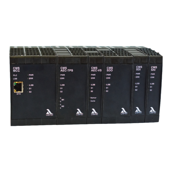
- Page 45 CMS Components 4.3.2 Technical Data Fig. 4-11 AEC-VS photo Fig. 4-12 AEC-VS dimensional drawing Item number AEC-VS Actuator Extension Component - Variable Speed Type 668R2030-XX XX = dependent on the configuration Function Power supply 24 VDC ± 20 % (via plug-in connection from MCC)
- Page 46 CMS Components Signal inputs Namur Sensor supply: 8.2 V, max. 8.2 mA Pulse input for connecting inductive Conversion of the sensor recording into digital information: – Inactive: >2.1 mA Digital signal ON sensors with Namur interface accord- – Active/pulse: <1.2 mA Digital signal OFF...
- Page 47 CMS Components Outputs Digital output Non-safe, digital output Relay output, floating Voltage up to 230 VAC/50 Hz Rated current: 2 A, cos = 0.2 Fuse protec- Resettable/electronic 4.1 A max. (voltage-dependent) tion: Not resettable 5 A fast-acting Electrically safe separation from SELV power supply voltage of the...
- Page 48 CMS Components 4.3.3 Terminal Assignment Fig. 4-13 AEC-VS 230 VAC or 120 VAC terminal Fig. 4-14 AEC-VS 24 VDC terminal assignment assignment...
- Page 49 CMS Components 4.3.4 Functional Description The AEC-VS is equipped with: • Pulse input for connecting inductive proximity sensors with NAMUR interface • Pulse input for connecting inductive proximity sensors with 3-wire interface • Analogue input for the connection of rotary encoders with current interface 0/4 - 20 mA or position indicators from actuator drives with current interface 0/4 - 20 mA •...
- Page 50 CMS Components Burner firing-rate In operation Yel- – Flashing at 2 Hz: – Flashing at 2 Hz: ICOM initialising PEC identification activated. – Permanent light: ICOM successfully initialised * Passive mode = PEC not taught-in Colour Description Yellow Each pulse at the Namur input switches the LED. The LED flashes at half pulse frequency.
-
Page 51: For Your Safety
CMS Components 4.3.8 Sensors Suitable for CMS The following sensors are tested with the CMS: • Namur sensor type 663R8101 • 3-wire sensor type 663R8103 SDI - Safe Digital Input 4.4.1 For Your Safety See chapter 2 Safety 4.4.2 Technical Data... - Page 52 CMS Components Fig. 4-17 SDI dimensional drawing Part number SDI Safe Digital Input component Type 668R0400-XX XX = depends on configuration Function Supply voltage 24 VDC +/−20%, SELV (by plug connection from MCC) Current draw Min: 40 mA Max.: 45 mA Power consumption 1.5 W max.
- Page 53 CMS Components Environmental conditions Temperature range −40 … +80°C (non-condensing) Storage Climatic conditions Class 1K3 according to DIN EN 60721-3-1, 5-95% Mechanical conditions Class 1M2 according to DIN EN 60721-3-1 Temperature range −40 … +80°C (non-condensing) Electrical safety IP rating according to DIN EN 60529...
- Page 54 CMS Components 4.4.3 Terminal Assignment Fig. 4-18 Terminal assignment SDI 230 VAC or Fig. 4-19 Terminal assignment SDI 24 VDC 120 VAC...
-
Page 55: Leds
CMS Components 4.4.4 Functional Description Each SDI module provides up to failsafe digital inputs which can be used to expand the I/O of a CMS system. The safe digital inputs are assigned using the CMS configuration software. 4.4.5 LEDs Col-... -
Page 56: Interfaces
CMS Components 4.4.6 Connection Diagram Fig. 4-20 SDI connection diagram 4.4.7 Interfaces Failsafe communication via iLSB. -
Page 57: Sdo - Safe Digital Output
CMS Components SDO - Safe Digital Output Extension Module for Failsafe Digital Outputs 4.5.1 For Your Safety See chapter 2 Safety 4.5.2 Technical Data Fig. 4-21 SDO photo Fig. 4-22 SDO dimensional drawing... - Page 58 CMS Components Part number SDO Safe Digital Output component Type 668R0500-XX XX = depends on configuration Function Supply voltage Module 24 VDC (by connecting plugs from MCC) Outputs 230 V/120 V +10/-15 %, 47-63 Hz, 24 VDC ± 20 % Backup fuse max.
-
Page 59: Terminal Assignment
CMS Components 4.5.3 Terminal Assignment Fig. 4-24 Terminal assignment SDO 24 VDC Fig. 4-23 Terminal assignment SDO 230 VAC or 120 VAC... -
Page 60: Functional Description
4.5.4 Functional Description SDO is a module which is designed for failsafe digital outputs. It enhances the CMS system. SDO is equipped with 8 failsafe digital outputs These are assigned to the CMS system by soft- ware functions. 4.5.5 LEDs... -
Page 61: Connection Diagram
CMS Components 4.5.6 Connection Diagram Fail-safe relay outputs Fig. 4-25 SDO connecting diagram 4.5.7 Interfaces Failsafe communication via iLSB. -
Page 62: Sai - Safe Analogue Input
CMS Components SAI - Safe Analogue Input 4.6.1 For Your Safety See chapter 2 Safety 4.6.2 Technical Data Fig. 4-26 SAI photo Fig. 4-27 SAI dimensional drawing... - Page 63 CMS Components Part number SAI Safe Analogue Input Component Type 668R0600-XX XX = depends on configuration Function Supply voltage 24 VDC ±20% (by connecting plug from MCC) Current draw Min: 65 mA Max: 350 mA Power consumption 8.4 W Housing Dimensions (H ×...
-
Page 64: Terminal Assignment
CMS Components 4.6.3 Terminal Assignment Fig. 4-28 SAI 230 VAC terminal assignment 4.6.4 Functional Description Terminal configuration Six inputs can be configured for each SAI by ’SAI terminal configuration’. The SAI parameter array is initiated based on the sequence number of the SAI module ad- dress. -
Page 65: Leds
Using an analogue input as a digital input The analogue inputs of the CMS (MCC or SAI) can be used as digital signals. To do so, the IO configuration must be set as follows: How to set the IO configuration to analogue-digital usage 1. -
Page 66: Connection Diagram
CMS Components Burner firing-rate In operation iLSB Yel- – Flashing at 2 Hz: – OFF and ERR-LED OFF: iLSB initialising Passive mode – Permanent light: – OFF and ERR-LED ON: iLSB successfully initialised Fault during system layer initialisation – Permanent light: iLSB communication OK, Module is in operation –... - Page 67 CMS Components SAI terminal assignment Pulses – NAMUR Pulses – 3-wire Pt100/Pt1000 0 … 10 V 0 … 20 mA Connection examples +24 VDC from MCC (e.g. X33 pin 2/4) Pin 1 Ref+ Pin 2 SAI X11–X16 Pin 3 Pin 4 Fig.
- Page 68 CMS Components +24 VDC from MCC (e.g. X33 pin 2/4) Pin 1 Ref+ Pin 2 SAI X11–X16 Pin 3 Pin 4 Fig. 4-32 0/4 … 20 mA signal transmitter, 2-wire (here: pressure transmitter) Pin 1 Ref+ Pin 2 SAI X11–X16...
-
Page 69: Interfaces
CMS Components Type of Configuration Software Configuration Software Input Sensors Connection Parameter IO-Matrix Non-fail- 1 per input = 1 nsi see Fig. 4-29 SAI connection dia- P 1270 Mapping as nsi AI safe signal gram Bit 0 ... 6: Function... -
Page 70: Ui400 - User Interface
CMS Components UI400 - User Interface 4.7.1 For Your Safety See chapter 2 Safety 4.7.2 Technical Data Fig. 4-35 UI400 photo Fig. 4-36 UI400 mounting dimensions Cut-out for UI400 installation: 108 mm × 61 mm: Part number UI400 user interface, connection via LSB... -
Page 71: Functional Description
CMS Components Function Current draw : 32 mA – with screen saver, backlight OFF : 16 mA – with max. 20 mA/10 V at setpoint outputs. Housing Dimensions (H × W × D) [mm] 64 × 112 × 26 Weight [kg]... -
Page 72: Interfaces
For Your Safety • Only use with SELV supply voltage in accordance with DIN EN 60730. • If this is not available, the GUI must be supplied by the 24 V output of the CMS. 4.8.2 Technical Data 4.8.2.1 GUI607 Fig. - Page 73 CMS Components Fig. 4-40 GUI607 mounting dimensions in mm Cut-out for GUI706 installation: 187 mm × 136.5 mm for a sheet thickness of 2 mm Part number GUI607 graphical user interface, 7" 24 VDC, panel installation Type 668R1000 Function Supply voltage 24 VDC −15/+20% SELV...
- Page 74 CMS Components Environmental conditions Operation Temperature range 0 - +55 °C (non-condensing) Relative humidity Max. 85%, non-condensing Transport Temperature range −20 - +70 °C (non-condensing) Relative humidity Max. 85%, non-condensing Storage Temperature range −20 - +70 °C (non-condensing) Relative humidity Max.
-
Page 75: Gui615
CMS Components 4.8.2.2 GUI615 Fig. 4-41 GUI615 Fig. 4-42 Ensure unobstructed air circulation! >20 mm Fig. 4-43 Dimensional drawing GUI615... - Page 76 CMS Components Part number GUI615 graphical user interface, 7" 24 VDC, panel installation Type 668R1004 Function Supply voltage 24 VDC −15/+20% SELV max. AC voltage component 5% with inverse-polarity protection Maximum backup fuse 10 A slow-blow Power consumption Module electronic current consumption Type 0.8 A, max.
-
Page 77: Connection Diagram
CMS Components 4.8.3 Functional Description The GUI6xx models are HMIs for the configuration and monitoring of a burner. The following models are available: • GUI 607 with 7" screen diagonal • GUI 610 with 10" screen diagonal • GUI 615 with 15" screen diagonal 4.8.4... -
Page 78: Interfaces
CMS Components Fig. 4-45 GUI615 connection diagram Description Description Display 16,5 " EtherCAT LEDs: PWR, Run/Stop, Error CAN-Bus LEDs: Power, digital I/O RS-232/RS-485 Ground Do not use Power supply, digital inputs Do not use and outputs Termination resistor CAN (120 ) Analogue inputs Terminating resistor RS-485 (120 ) -
Page 79: Router
CMS Components Router 4.9.1 For Your Safety • When connecting the CMS to a local Ethernet LAN or WLAN, the applicable IT security guidelines must be respected. • The network must be protected against any unauthorised access. 4.9.2 Functional Description Recommendation for Ethernet-based communication: Weidmüller IE-SW-BL05-5TX Fast Ethernet. -
Page 80: Functional Description With Process Diagrams
Functional Description with Process Diagrams Functional Description with Process Diagrams The following process diagrams are examples only. The actual process diagrams will depend on the CMS configuration. Basic Burner Sequencer Functionality NOTICE The special points required, such as pre-purge position and post-purge position must be set. - Page 81 Functional Description with Process Diagrams Signal bar Significant times and their parameters Standard Signal must be present. Parasitic light monitoring time P803 5.0 s Signal must not be present. Pre-ventilation time P318 1 - 999 s Signal can be present. Transformer pre-activation time P309 3.0 s...
-
Page 82: Default Process Flow For Gas Modulating Without Pilot Burner
Functional Description with Process Diagrams 5.1.2 Default Process Flow for Gas Modulating Without Pilot Burner Fig. 5-3 Process sequence chart for gas modulating without pilot burner Signal bar Significant times and their parameters Standard Signal must be present. Parasitic light monitoring time P803 5.0 s Signal must not be present. -
Page 83: Default Process Flow For Oil Modulating With Pilot Burner
Functional Description with Process Diagrams Fig. 5-4 Gas train for standard process flow gas modulating without pilot burner Fuel valve on gas side Actuator drive for gas damper Fuel valve on burner side Min. gas pressure monitor 5.1.3 Default Process Flow for Oil Modulating With Pilot Burner Fig. - Page 84 Functional Description with Process Diagrams Signal bar Significant times and their parameters Standard Stabilization time P310 3.0 s safety time P308 3.0 s Control release delay time P380 0.0 s Block and bleed of the gas train P334 3.0 s Post-ventilation time P319 0.0 s...
-
Page 85: Default Process Flow For Oil Modulating Without Pilot Burner
Functional Description with Process Diagrams 5.1.4 Default Process Flow for Oil Modulating Without Pilot Burner Fig. 5-7 Process sequence chart for oil modulating without pilot burner Signal bar Significant times and their parameters Standard Signal must be present. Parasitic light monitoring time P803 5.0 s Signal must not be present. -
Page 86: Additional Burner Sequencer Functionality
Functional Description with Process Diagrams Additional Burner Sequencer Functionality 5.2.1 Start Without Pre-Purge NOTICE The external signal for pre-purge suppression must be fail-safe. 5.2.1.1 Requirements NOTICE This function may only be activated if local regulations and the system configuration permit a burner start without pre-purge or if sufficient pre-purge is ensured by other measures. -
Page 87: Standby Mode
Functional Description with Process Diagrams 5.2.2 Standby Mode NOTICE The pilot flame scanner must either be approved for continuous operation or the pilot flame is monitored together with the main flame with a flame scanner approved for continuous opera- tion. NOTICE For the standby function, please consult both the Installation Manual and Commissioning Manual, and also take into account the specific requirements for the combustion system. -
Page 88: Functional Description
Functional Description with Process Diagrams 5.2.2.4 Functional Description Fig. 5-9 Process sequence chart for standby operation with the example of gas Signal bar Significant times and their parameters Standard Signal must be present. Filling time of the gas path P313 2.0 s Signal must not be present. -
Page 89: Purging The Fuel Train
Functional Description with Process Diagrams Fig. 5-10 Gas train for standard sequence for gas modulating with pilot burner Fig. 5-11 Oil train for standard process flow oil modulating with pilot burner Gas side fuel valve Gas damper servomotor Burner side fuel valve Min. -
Page 90: Required Parameters
The purge process is only started once a flame has been established. The function can be used only if CMS is configured to ’Start with pilot burner’. After the stabilisation time t2 for the pilot flame is complete (P 310), the system waits until the oil actuator has reached the purge position. - Page 91 Functional Description with Process Diagrams NOTICE This function is active only from software version 2.0. Process Diagram 'Purging after Operation' Fig. 5-12 Process sequence chart for purging oil gun Control Transformer pre-activation time P309 0.0 s - 40.0 s Burner OFF Post-ventilation time P 319 0.0 s - 999 s Duration of purging P 810...
-
Page 92: Purging With Digital Input
Restarting with Extended 2 Safety Time when Igniting - Flag CMS sets a failsafe flag which stores the outcome of whether the last oil gun purge was suc- cessful or not. If a purge was successful then the oil gun/lance is deemed to be empty and the 2... -
Page 93: Operating Modes For The 'Purging Fuel Train Function
Functional Description with Process Diagrams After the pre-ventilation time has elapsed, the compound moves to the ignition point and the pilot burner is started. The spark igniter remains active throughout the stabilisation time and the entire purging time. The fuel valves do not open. The purging time starts after the stabilisation time. -
Page 94: Required Parameters
Functional Description with Process Diagrams 5.2.4.3 Required Parameters P no. Description Attributes Control and monitoring of the pilot burner V1.0.0.0 (0-Start without; 1-Start with; 2-even active in operation; 3-Start with, only pilot flame may be present during ignition; 4-active in operation, with continuous operation monitoring, only pilot flame may be present during ignition;... -
Page 95: Cpi/Poc - Closed Position Indication/Proof Of Closure
Functional Description with Process Diagrams Signal bar Significant times and their parameters Standard safety time P305 4.0 s Stabilization time P310 3.0 s safety time P308 3.0 s Control release delay time P380 0.0 s Block and bleed of the gas train P334 3.0 s Post-ventilation time... -
Page 96: Valve Leakage Test
Functional Description with Process Diagrams 5.2.6 Valve Leakage Test NOTICE The gas pressure test switch and design and volume of the test section pipework must be set and designed such that the valve test system reliably detects even the smallest gas leakage by the valve testing system at maximum combustion thermal output. -
Page 97: Functional Description
> min = 0. The CMS checks this and if true then Main gas valve 1 is opened for a short time to allow gas to flow into the test line. -
Page 98: Valve Leakage Test Flow Chart
Functional Description with Process Diagrams 5.2.6.4 Valve Leakage Test Flow Chart Fig. 5-15 Process flow for valve leakage test... -
Page 99: Process Sequence Chart
Functional Description with Process Diagrams 5.2.6.5 Process Sequence Chart Principle sequence of a valve leakage test Fig. 5-16 Principle sequence of a valve leakage test Signal bar Significant times and their parameters Standard Signal must be present. Filling time of the gas train* P313 2.0 s Signal must not be present. - Page 100 Excess pressure configured at pressure monitor switching point sw e Excess pressure at gas valve V2 output at the time of block and bleed out e Atmospheric pressure (average of 101.3 kPa at sea level) Test volume between the valves test Configured test time CMS...
-
Page 101: Suggested Circuit For Venting
Excess inlet pressure at gas valve V1 in e Atmospheric pressure (average of 101.3 kPa at sea level) Test volume between the valves test Configured test time CMS 5.2.6.7 Suggested Circuit For Venting Block and bleed by the roof Gas-side valve Burner-side valve Gas min. -
Page 102: Electronic Ratio Control System
Commissioning Recommendation: For commissioning of the CMS system, program the special points for OFF and for pre-venti- lation in the current curve set and all curve sets used in succession. Particularly when setting while the burner is in operation, the actuator positions for pre-venti- lation and OFF (CLOSE) must be defined and accessible, see chapter 8.9 Settings . -
Page 103: Actuators With Tps Control
5.3.6 Logical Actuator Channels Channel functions Logical channels that are to be controlled by the CMS electronic ratio control must be config- ured with a channel function. Parameter value >0. Flue gas channels In opposite to existing products, flue gas ducts no longer show any special behaviour at the ignition point. -
Page 104: Burner Firing Rate Controller
Purchase option: This function must be purchased and mapped. 5.4.2 Required Inputs/Outputs The actual value is assigned to the analogue input in the IO-Matrix dialogue of the CMS Re- mote Software. The setpoint values can be switched by means of the digital input signal ’PLC firing rate con- troller input setpoint changeover’. -
Page 105: I Term
Functional Description with Process Diagrams 5.4.3.2 I Term The firing rate controller can use an actual current value (mA), the boiler temperature (°C, °F) or the steam pressure (bar, psi) as the actual value for control. P 61 defines the unit of the actual value. -
Page 106: Controlled By Atmospheric Conditions
Functional Description with Process Diagrams 5.4.3.4 Controlled by Atmospheric Conditions P no. Description Attributes Controller setpoint 1 (for constant control/min. value for control by atmospheric condition) Controller setpoint 1 minimum. Setting the minimum set point for the controller controlled by Write: 0/GUI/UI atmospheric conditions in °C or bar. -
Page 107: Burner Shut-Off
Functional Description with Process Diagrams P no. Description Attributes Start-up sequence: firing-rate [Digit] V1.0.0.0 Start-up output in digit depending on internal firing-rate. Write: 0/GUI/UI Enter the burner firing-rate with which the burner shall start in the start-up sequence. Read: 0 Default: 0 Min: 0 Max:999... -
Page 108: Functional Description
Burner Shut-off with Switching Thresholds: Shut-off threshold: If the firing rate controller detects that the boiler temperature or steam pressure exceeds a configured threshold (switch-off threshold), it removes the signal ’burner ON’ in the CMS and sets the logical signal ’burner OFF’. Switch-on threshold:. -
Page 109: Commissioning
Programming of Curves Accessing the CMS menu ’RC curves’ and submenus (AL1) Fig. 6-1 Accessing the CMS menu ’RC curves’ and submenus The curve screen shows the setpoint curves for the channels (ratio controller) per curve set. The user can switch between showing a curve-based format (setpoint graphic) and a display... -
Page 110: Programming Curves
• setpoint graphic • curve table To change a curve in the CMS, the CMS must first be switched into the START CONFIGU- RATION mode. NOTICE This function is relevant for safety. The function must be confirmed a second time within 8 seconds. - Page 111 Commissioning RC curves: programming the ignition point (AL1) 1. Click the ’Start configuration’ button. 2. Enter a password if required to do so. 3. Dialogue box: ’Start configuration with fan?’ If a fan is present, the fan must be activated for programming the curve. Feedback would otherwise be absent.
-
Page 112: Configuring Special Points
Configuring special points with the CMS Remote Software (AL1) Special points determine how wide the various valves/dampers should open or close at certain points in time. Fig. 6-3 Configuring special points with the CMS remote software Selecting the active channels Graphical representation and configuration of special points... -
Page 113: Configuring The Range Limits
Configuring the Range Limits Configuring the range limits with the CMS remote software (AL1) Fig. 6-4 Starting the range limit configuration process Step 2 Step 1 Fig. 6-5 Reading in the range limits 2 – CMS remote software Step 3... -
Page 114: Shut-Off Limits
• The CMS parameters are set in such a way that the tolerances in the direction of air defi- ciency are 0 digits, i.e. there is only a tolerance to the excess air side. - Page 115 Commissioning 1. Note the ’general tolerance limit’ for each channel used from parameter 520.1 - 520.10 (AL0). 2. Start burner 3. Open ’Curves/Electronic ratio Ctrl.’ (AL1) 4. Adjust the required firing rate pint with the arrow buttons. (right/left) 5. Wait until the system has reached the point. 6.
-
Page 116: Checking The O2 Effect
NOTICE If the factory-set switch-off limit of 0.4 vol.% O is too low for the application, it can be raised using the CMS Remote Software (AL4). If necessary, contact LAMTEC Support: support@lamtec.de +49 (0) 6227 6052-33 ’How to’ see chapter 6.3.4.1 Run to Shut-off Limits... -
Page 117: Operating Control And Displays
Operating Control and Displays Operating Control and Displays Operation, Controls and Display with UI400 Display BACK key Cursor keys ENTER key Fig. 7-1 User interface Display The display shows in pictogram: • the menu structure • operating status • parameters •... - Page 118 Operating Control and Displays INFO MANUAL SETTINGS INFO Select INFO path for information about the following: • Burner • Faults/Fault history • Software version • Display of check sums • Serial number • Actuator positions (current damper position for each channel) •...
-
Page 119: Main Menu
Operating Control and Displays 7.1.2 Main Menu INFORMATION menu path [selected] Display of canal Bar graph of internal firing rate in % (0 - 100) Fuel train MANUAL menu path SETTINGS menu path Release level Window number Fig. 7-2 Main menu For a complete description of the display symbols, see chapter 12.6 Display Symbols NOTICE The parameters of release level 1 must be protected by a password against unauthorised... -
Page 120: Burner Details
Operating Control and Displays 7.1.3.1 Burner Details Displaying Operating Hours, Burner Starts and Firing Rate Controller Settings Display of operating hours Number of operating hours in total (device connected with mains) Number of operating hours in oil operation Number of operating hours in gas operation Display of burner starts Number of burner starts in oil operation Number of burner starts in gas operation... -
Page 121: Recalling Fault History
Operating Control and Displays 7.1.3.2 Recalling Fault History Displaying Burner Faults Fault code (Last 10 faults are stored, No. of operating hours when no. 01 is the latest fault) fault has occurred D1 Diagnostic code 1 Duration of the fault D2 Diagnostic code 2 NOTICE Information concerning fault and diagnostic codes can be found in the list of fault codes. -
Page 122: Software Version
How to unlock BT300 A fault is pending and the ENTER key is flashing. 1. Press ENTER key. CMS is not locked anymore. Changing from fault unlock to main menu: A fault is pending and the ENTER key is flashing 1. -
Page 123: Display Of Check Sums
0 ... 4 = Check sum, access levels 0 ... 4 The checksums are generated from the device parameters. The CMS calculates one check- sum for the parameters of each access level (0, 1, 2 or 4). The UI400 indicates the checksums in hexadecimal code. -
Page 124: Manual Menu Path
CAUTION! If you carry out a manual start-up via display CMS no longer responds to ’Burner ON’ signal input at connector X10.2. Therefore that limiters, monitors and other similar safety functions must not be operated with this input! -
Page 125: Settings Menu Path
Operating Control and Displays 7.1.5 Settings Menu Path Password Display settings Read configura Configure curve for program tion for continu- sequence ous output Delete curve Configure Configure Configure controller password display NOTICE The level 1 parameters must be protected against unauthorised modification by setting a password different to ’000000’. -
Page 126: Program Sequence
Pilot burner Set duration of pre-purge period Parameter number UI Parameter modifications are transferred CMS = Parameter number CMS Parameter modifications are discarded NOTICE Both values are identical – Confirm with The values are different – Cancel with... - Page 127 Operating Control and Displays NOTICE Pre-purge starts as soon as damper reaches pre-purge position and - if you use a VSM - the last but one point of electronic ratio curve is passed. NOTICE The second to last channel’s position must be lower than the position of the last curve point. Set duration of the post-purge NOTICE Both values are identical –...
- Page 128 Operating Control and Displays Valve Leakage Test Valve leakage test ON/OFF P802 P802 = 0 = Valve leakage test OFF P802 = 1 = If valve leakage test before ignition is configured, the test runs during ignition. P802 = 2 = If valve leakage test before ignition is configured, the test runs after pre-purge.
-
Page 129: Configuring The Servomotors
Operating Control and Displays Activate pilot burner Pilot burner ON Pilot burner OFF 7.1.5.3 Configuring the Servomotors Displaying the Servomotors’ Configuration Channel 1 = OIL = oil Channel 2 = AIR = air Channel 3 = OFF = OFF Channel 4 = OFF = OFF (optional channel) - Page 130 Operating Control and Displays 7.1.5.4 Setting Curves How to set the servomotor’s curve sets Firing rate point - from ignition position up to 999 Setpoint value channels 1 ... 3 Actual value channels 1 ... 3 (in this case: channel 1 = oil, channel 2 = air channel 3 = OFF) Curve data for this firing rate point are stored yet NOTICE...
-
Page 131: Deleting Curves
Operating Control and Displays 7.1.5.5 Deleting Curves Delete firing-rate curve... -
Page 132: Adjusting Controller
Operating Control and Displays 7.1.5.6 Adjusting Controller PID controller settings CO/O controller settings • Mode • ON/OFF • Speed • Correction mask • Physical units • Correction spreading... -
Page 133: Changing Password
Operating Control and Displays 7.1.5.7 Changing Password Change password on UI400 7.1.5.8 UI400 Settings Set display of UI400 Set brightness. Set contrast Set waiting time for screensaver Change-over degrees/Fahrenheit NOTICE The screensaver cannot be set to 0! -
Page 134: Operation, Controls And Display With Gui607/610/615
Operation, Controls and Display with GUI607/610/615 The GUI (graphical user interface) is a touch-sensitive panel. The panel visualises the system with the parameter and curve data from the devices on the LSB (LAMTEC SYSTEM BUS). The GUI is used to access, edit and store values. -
Page 135: Process Diagram And Menu Navigation
Operating Control and Displays 7.2.1 Process Diagram and Menu Navigation Start screen From the process diagram or start screen, all of the other menus and submenus can be ac- cessed by touching the surface of the screen. Fig. 7-4 GUI6xx – start screen/process diagram Burner ON icon Flue gas temperature in °C Burner status display... - Page 136 Operating Control and Displays Navigating in menus and submenus Fig. 7-5 GUI6xx – navigating in menus and submenus, part 1 First submenu Cancel Access alarm history Confirm input Touching anywhere in the shaded area Manual burner firing rate opens the first submenu 1 screen Back button Password entry...
- Page 137 Operating Control and Displays Typical layout of icons and text on the status bar: Status Additional Message Operating Load bar Curve set status mode W001 Message text Menu structure: If a submenu is entered, the menu icon is inverted and shifts up to the top left-hand corner. If the next level down is entered, the icon of the previous menu level is retained and the new menu icon is displayed next to it.
-
Page 138: Password
Operating Control and Displays 7.2.2 Password Entering the 4-character password with the aid of the arrow keys (AL0). A combination of letters and digits is possible. 4 access levels are available. NOTICE The password entry window can be accessed from all menus and submenus. Fig. -
Page 139: Burner Settings Menu
Operating Control and Displays 7.2.3 Burner Settings Menu Accessing the burner statistics (AL1) Fig. 7-9 GUI6xx – accessing the burner settings menu... - Page 140 Operating Control and Displays Accessing information about digital inputs and outputs (AL1) Fig. 7-10 GUI6xx – information about digital inputs and outputs...
- Page 141 Operating Control and Displays Accessing electronic ratio control information (AL1) Fig. 7-11 Electronic ratio control information...
- Page 142 Operating Control and Displays Accessing channel information (AL1) Fig. 7-12 GUI6xx – channel information...
- Page 143 Operating Control and Displays Accessing purging settings NOTICE Note: a minimum of access level 2 is required for the settings in the following menus! Fig. 7-13 GUI6xx – purging menu...
- Page 144 Operating Control and Displays Accessing the leakage test time settings (AL1) Fig. 7-14 GUI6xx – setting the valve leakage test time...
- Page 145 Operating Control and Displays Accessing the pilot burner settings (AL1) Fig. 7-15 GUI6xx – accessing the pilot burner settings...
- Page 146 Operating Control and Displays Editing curves and individual curves (AL1) Fig. 7-16 Editing curves and individual curves Increase value Save curve point Decrease value Delete curve point Increase firing rate Activate automatic mode Decrease firing rate...
- Page 147 Operating Control and Displays Set upper and lower stop for the actuators (AL1) Fig. 7-17 Set upper and lower stop for the actuators...
- Page 148 Operating Control and Displays Channel configuration (AL1) Fig. 7-18 Channel configuration...
-
Page 149: Burner Firing-Rate Controller Menu
Operating Control and Displays 7.2.4 Burner Firing-Rate Controller Menu Accessing burner firing-rate controller information (AL1) Fig. 7-19 Burner firing-rate controller information... - Page 150 Operating Control and Displays Accessing the burner firing-rate controller settings (AL1) Fig. 7-20 Burner firing-rate controller settings...
- Page 151 Operating Control and Displays Accessing the burner firing-rate controller input configuration (AL3) Fig. 7-21 Burner firing-rate controller input configuration...
- Page 152 Operating Control and Displays Accessing the burner firing-rate controller units (AL3) Fig. 7-22 Burner firing-rate controller units...
-
Page 153: Co/O2 Burner Optimisation Menu
Operating Control and Displays 7.2.5 CO/O Burner Optimisation Menu Accessing the information for the burner's CO/O optimisation (AL1) Fig. 7-23 Burner optimisation information... - Page 154 Operating Control and Displays Accessing the CO/O settings (AL2) Fig. 7-24 CO/O settings menu...
-
Page 155: Flame Monitoring System Menu
Operating Control and Displays 7.2.6 Flame Monitoring System Menu Accessing the flame monitoring system information (AL1) This menu cannot be used to make any changes. Fig. 7-25 Flame monitoring system information... -
Page 156: System Functions Menu
Operating Control and Displays 7.2.7 System Functions Menu Accessing the system information (AL1) Fig. 7-26 System information menu Accessing the system CRCs (AL1) - Page 157 Operating Control and Displays Fig. 7-27 System CRCs menu...
- Page 158 Operating Control and Displays Accessing the fault history (AL1) Fig. 7-28 Fault history menu Accessing dataset handling (AL3) Saving and restoring a dataset:...
- Page 159 Operating Control and Displays Fig. 7-29 Dataset handling menu A dataset can be transferred from the CMS and saved with ’Store’. A dataset can be transferred/restored to the CMS with ’Restore’. Accessing module configuration (AL1) The menu shows an overview of the modules deployed in the system.
- Page 160 Operating Control and Displays Fig. 7-30 Module configuration menu Accessing the change password menu (AL1) Change password 1. Enter old password. 2. Enter new password. 3. Confirm new password.
- Page 161 Operating Control and Displays Fig. 7-31 Change password menu Accessing the CMS IP setting menu (AL2) Change IP address 1. Tap the address field 2. Enter the IP address in the dialogue box. 3. Tap the dialogue box to confirm and save the address entered.
- Page 162 Operating Control and Displays Fig. 7-32 IP setting menu...
-
Page 163: User Settings
Operating Control and Displays 7.2.8 User Settings Accessing the display settings Fig. 7-33 Display settings menu... - Page 164 Operating Control and Displays Accessing the language settings (AL1) Fig. 7-34 Language settings menu...
-
Page 165: Operation, Controls And Display With Cms Remote Software
PC (as a backup). These dataset backups can also be load- ed back into the CMS at a later point in time in order to restore a specific CMS state. The previous pages have described the most important activities that can be completed using the CMS Remote Software. - Page 166 Operating Control and Displays Fig. 7-35 Installation...
- Page 167 Operating Control and Displays Fig. 7-36 Installation...
-
Page 168: Offline/Online
Online 7.3.2.1 Offline Mode In offline mode, there is no continuous connection to CMS (no parameter setting possible). Offline mode is used simply as a display option for the data. Previously stored datasets from end devices can therefore be displayed. -
Page 169: Online Mode
The permanent connection to the end device is monitored from both sides with a time-out. While establishing connection to the device all functions are locked. 7.3.2.3 Connecting the CMS to the PC Access code/access levels See chapter 7.3.3.3 Access Rights Menu Access code/access levels See chapter 7.3.3.3 Access Rights Menu... - Page 170 Operating Control and Displays Fig. 7-40 Establish a remote connection to the CMS 3. Configuring the IP address The IP addresses must be identical. Fig. 7-41 Connection data – enter target IP 4. Establishing a connection...
- Page 171 Operating Control and Displays The connection between PC and CMS is established. Fig. 7-42 Connection data – establishing a connection 5. Close the window Display of the connected CMS Fig. 7-43 Device overview – CMS remote software...
- Page 172 Operating Control and Displays First connection with the device Fig. 7-44 Register the first connection with the device and enter access level Password entry required!
-
Page 173: Cms Remote Software User Interface
Operating Control and Displays 7.3.3 CMS Remote Software User Interface Fig. 7-45 CMS remote software start screen Select functions Device type Menu bar Software status – here "ONLINE" Device overview Fig. 7-46 CMS Remote Software icons on lower menu bar... -
Page 174: Dataset Menu
Operating Control and Displays 7.3.3.1 Dataset Menu Fig. 7-47 Dataset menu in online mode The ’Dataset’ menu path can be used to: • Open and save a dataset • Save or load a protected dataset • Compare datasets • Exit from the application Opening a dataset 1. - Page 175 Operating Control and Displays Saving a protected dataset 1. Same procedure as for saving a normal dataset. NOTICE When saving a protected dataset, all data is saved, regardless of the user's personal level of authorisation (= access level). A protected dataset cannot be opened or edited. A protected dataset can be read into the device regardless of the user's level of authorisation (= access level).
- Page 176 Operating Control and Displays Fig. 7-49 Loading a protected dataset into the device...
- Page 177 Operating Control and Displays Comparing datasets 1. In the menu, click ’Compare dataset’. 2. Proceed as shown below. Fig. 7-50 Comparing CMS datasets 1 Current dataset 2 Open the dataset to be com- 3 The differences are shown pared here NOTICE The dataset comparison feature is used for checking or troubleshooting.
-
Page 178: Connection Menu
7.3.3.2 Connection Menu Fig. 7-51 CMS connection menu The "Connection" menu path can be used to: • Make a device selection • Assign CMS-Remote • Establish a connection (set online) • Drop a connection Device selection Fig. 7-52 CMS device selection menu... -
Page 179: Access Rights Menu
Operating Control and Displays Set online: see chapter 7.3.2.1 Offline Mode Drop connection: Drops the connection to the CMS, see chapter 7.3.2.1 Offline Mode CMS remote registration (AL1) Fig. 7-53 CMS remote registration menu This procedure must be completed once for each MCC. - Page 180 The parameters of release level 1 must be protected by a password against unauthorised changes. This password must differ to the default settings. Fig. 7-55 Changing the CMS level 1 password Changing the level 1 password 1. Select the ’Change level 1 password’ menu option.
- Page 181 Operating Control and Displays Changing the customer code Fig. 7-56 Changing the customer code and level 2 password The customer code must be entered when commissioning a new device. 1. Access rights menu. 2. Select ’Change customer code’. 3. Enter new customer code. 4.
-
Page 182: Cms Menu
Operating Control and Displays 7.3.3.4 CMS Menu The "CMS" menu path provides access to: • Parameters • Configuration • Safety • VR curves • CO/O data • Histories • Input/output measurement values • Manual burner firing rate specification • Cold check •... - Page 183 Operating Control and Displays Parameter Accessing the ’All parameters’ submenu Fig. 7-58 CMS all parameters window 1 Enter the password (padlock symbol) 2 A search using groups is possible Setting and changing values 1. Double-click to select the parameter value.
- Page 184 Operating Control and Displays Submenu ‘Firing rate controller parameters’ Fig. 7-59 CMS firing rate parameter 1 Enter the password (padlock symbol) Setting and changing values 1. Enter the values numerically Alternatively: Set the values with the up/down arrow keys 2. Confirm the values with the ENTER-key or chose another parameter.
- Page 185 Operating Control and Displays Accessing the ’ O trim’ submenu Fig. 7-60 CMS parameters for O trim window Setting and changing values 1. Enter values numerically. 2. Confirm value with the ENTER key or select a different parameter. NOTICE Only parameters at the current access level can be changed! All parameters not at the current access level are greyed-out and cannot be changed.
- Page 186 Operating Control and Displays Accessing the ’CO Controller’ submenu Fig. 7-61 CMS Parameter - CO controller window Setting and changing values 1. Enter values numerically. Alternatively: Set values with arrow keys up/down 2. Confirm value with the ENTER key or select a different parameter.
- Page 187 Operating Control and Displays Accessing the ’Channel Configuration’ submenu Fig. 7-62 CMS parameters for channel configuration 1 Enter the password (padlock symbol) 2 Selection by pull down menus. NOTICE Only parameters at the current access level can be changed! All parameters not at the current access level are greyed-out and cannot be changed.
- Page 188 Operating Control and Displays Accessing the ’Correction’ submenu Fig. 7-64 CMS parameters for the correction 1 The password can be entered here (padlock symbol) Setting and changing values 1. Double-click to select the parameter value. 2. Confirm value with the ENTER key or select a different parameter.
- Page 189 A reset must be performed after changing some parameters. This is indicated with a system message. Accessing the ’AEC Parameter’ submenu Fig. 7-66 CMS AEC parameters 1 The password can be entered here (padlock symbol) Setting and changing values 1. Double-click to select the parameter value.
- Page 190 Operating Control and Displays Accessing the ’Restarting’ submenu Fig. 7-67 CMS Parameter for restarting the system 1 The password can be entered here (padlock symbol) Setting and changing values 1. Double-click to select the parameter value. 2. Confirm value with the ENTER key or select a different parameter.
- Page 191 Operating Control and Displays Configuration The first step in deploying a CMS is to register the individual modules with the system . This provides the system with details of the modules' serial numbers, functions and number . This data is then saved and filed as a dataset.
- Page 192 NOTICE Important: the mapped signals must be connected to the right terminals! The CMS offers the option of setting partial datasets that modify just one part of the parame- ters. These can be used to transfer only the IO matrix.
- Page 193 A total of 10 signal chains are available for linking together various input signals. These chains can consist of up to 16 links. These links must be assigned to a physical input via the I/O matrix in the CMS remote software package. Input functions already assigned (e.g. minimum gas pressure and maximum gas pressure) can also be assigned to a signal chain.
- Page 194 Fig. 7-72 Accessing the CMS parameter submenu ’Level CRCs’ Displays the CRC checksums for the individual user levels as calculated and stored in the device. RC Curves Accessing the CMS menu ’RC curves’ and submenus (AL1) Fig. 7-73 Accessing the CMS menu ’RC curves’ and submenus...
- Page 195 Operating Control and Displays The curve screen shows the setpoint curves for the channels (ratio controller) per curve set. The user can switch between showing a curve-based format (setpoint graphic) and a display in tabular format (curve table). CO/O2 Data Accessing CO/O data (AL1) Fig.
- Page 196 Operating Control and Displays History Accessing the ’Histories’ submenu Fig. 7-75 CMS submenu Histories The fault history shows the last 10 faults. The following information is output for the individual faults: • Fault number • Fault text • Affected module •...
- Page 197 Operating Control and Displays In addition, the ’Historical I/O data’ tab shows the state of the existing inputs and outputs as a time sequence. Fig. 7-77 Showing the state of the inputs and outputs Inputs/Outputs, Measurement Values Accessing inputs, outputs and measurement values The menu provides an overview of: •...
- Page 198 Operating Control and Displays 1 Digital inputs 2 Digital outputs 3 PLC Signals 4 Analogue measurement values...
- Page 199 4 Messages Manual Burner Firing Rate Presetting Accessing the ’manual burner firing rate’ submenu Fig. 7-78 CMS manual burner firing rate window Setting and changing values 1. Select parameter value internal/external value 1/2. Set value with arrow keys up/down and confirm with the ENTER key 2.
- Page 200 Operating Control and Displays Cold Check Accessing the cold check (AL1) Fig. 7-79 Cold check menu with submenus Performing a cold check 1. In the menu, click ’Cold check’. The screen for performing a check of the outputs opens. 2. Start the cold check with the ’Start cold check’ button. 3.
- Page 201 Operating Control and Displays Date/Time Date and time (AL1) In the date/time menu, the system time can be applied as follows. Fig. 7-80 Setting the date and time...
- Page 202 Operating Control and Displays Replacing a Module Fig. 7-81 Module replacement menu...
-
Page 203: Options Menu
Firmware update (AL1) Fig. 7-83 CMS firmware update menu Performing a firmware update 1. Switch the CMS to the firmware update mode. 2. Select the target device. 3. Warning: check the PEC ID! 4. Select the hex image for MP and WP (do not mix up the MP with the WP!) 5. - Page 204 Operating Control and Displays PLC update (AL1) Fig. 7-84 PLC update ’Chart/Trace’ (AL1) Fig. 7-85 CMS chart/trace 1 Start chart recording/pause/continue 2 Saving a record...
- Page 205 Operating Control and Displays All existing signals are always recorded together. The signals of interest must only be selected for visualisation. TCP-CAN Interface Establishing a TCP-CAN connection 1. In the menu, click "TCP-CAN interface". Fig. 7-86 TCP-CAN interface menu 2. Double-click the IP address in the bottom panel. This is then copied to the top input field for the target IP address.
- Page 206 Fig. 7-87 Language selection menu Selecting a language 1. In the menu, click "Language selection". 2. Select the language for the CMS remote software and confirm with "OK". Access Code Fig. 7-88 CMS access code menu 1. Enter the access code.
-
Page 207: Help Menu
7.3.3.6 Help Menu Help and version info (AL1) The "Help" menu path can be used to: • Access the help screens for the CMS remote software • Access information about the CMS remote software version Fig. 7-89 Help/version info menu Accessing help 1. -
Page 208: Co/O 2 Control
CO controller operation. If two or more systems of the CMS type are combined with a CO control device (e.g. two or more burners for a combustion chamber), the safe operation of the combustion must be en- sured with an additional flue gas monitoring system. -
Page 209: Requirements
CO/O Control Fig. 8-1 Correction range of the CO controller The upper limit of the correction range ensures that all errors leading to a movement of the controller in the direction of excess air only move the actuating devices up to an upper limit that is still safe. -
Page 210: Why Control Co
CO concentration rises noticeably. For this reason, CO control is not pos- sible with oil burners with a yellow flame. In the case of LAMTEC CO/O control, you can regulate on the basis of either CO or O , al- ternatively. -
Page 211: Overview Of Functions
CMS Combustion Management System with the option CO/O control • LT3-F Lambda Transmitter with KS1D combination probe The LAMTEC SYSTEM BUS (LSB) transmits the measured values and operating states to CMS. NOTICE The CO/O control only takes over when the probe is ready for operation. -
Page 212: Optimisation Strategy
CO/O Control 8.6.3 Optimisation Strategy The optimisation strategy includes searching for the optimum working point of the furnace near the emission edge, adjusting this accordingly, maintaining it, optimising further, if neces- sary, and monitoring. To do this, the fuel-air mixture is dynamically modified without influencing the power control unit in the direction of a lower lambda value (less air, more fuel). - Page 213 Basic value for deactivated O regulation and air deficiency In the CMS, the value for an inactive O trim and air deficiency value must be set as an offset to the neutral value, so that this value always tends in the direction of excess air.
-
Page 214: Display In The Case Of Active Co/O2 Control
CO/O Control 8.7.2 Display in the Case of Active CO/O2 Control 8.7.2.1 Display with Active CO Control The CO display replaces the O display as soon as CO control is active. CO actual value [ppm] – = air is reduced + = air is increased C = increasing firing rate c = falling firing rate... -
Page 215: Resetting Faults
Circuit Diagrams). 8.8.2 LAMTEC SYSTEM BUS (LSB) Fig. 8-6 CMS MCC with CO/O trim All data and operating states relevant for the control are transferred by LSB. For more information refer to the documents in chapter 1.1 Validity of these Instructions). -
Page 216: Settings
Setting the Correction Range and the Spread Factor and chapter Setting the Correction Range and the Spread Factor Activate CO/O trim with CMS Remote Software, see chapter Activating O2 Trim and chapter Setting the Correction Range and the Spread Factor 8.9.2... -
Page 217: Password Entry
Chapter 1.1 Validity of these Instructions. Information regarding password entry with UI400 see chapter 7.1.5.1 Password Information regarding password entry with GUI60x see chapter 7.2.2 Password Information regarding password entry with CMS Remote Software see chapter 7.3.3.3 Access Rights Menu 8.10 Installation and Commissioning 8.10.1... -
Page 218: Putting The Electronic Ratio Control System Into Operation
Activating CO Control – via UI400 Exiting SETTING Mode – via CMS Remote Software 10. Back up dataset from CMS and LT3-F using CMS Remote Software (download). Information on this is included in the basic documentation (publication no. DLT3140) The commissioning of CO/O control is now complete. -
Page 219: Combined O2/Co/H2 Measurement Lt3-F
8.10.3.1 Checking the Connection from LT3-F to BT300 by LAMTEC SYSTEM BUS. NOTICE The CMS then only has a connection via the LAMTEC SYSTEM BUS if the CO, or O value is displayed in the display window of the controller. -
Page 220: Operating And Comparing O
CO Measurements Information in the corresponding basic documents (see Chapter 1.1 Validity of these Instruc- tions). 8.10.4 Setting the CMS Correction Range Spread factor in case off correction of air actuator Spread factor (P725 seq.) = 10 Increase = 1.0 Mode +50 ... - Page 221 CO/O Control Spread factor (P725 seq.) Increase Mode +50 ... -50 Input 0 % ... 100 % Neutral value 50 % Correctional range* P 705 ff. Fig. 8-10 Correction with a spread factor of 20 Factory setting: Spread factor 10 Corresponds to 1.0 (i.e. no weighting) Spread factor >10 Correction effect increases as the burner efficiency increases Spread factor...
- Page 222 CO/O Control Spread factor in case off correction of air actuator Spreading factor = 10 (P701) = 1.0 Amplification +50 - -50 Mode 0% 100% Input 50 % Neutral value P 702 Correction range* Fig. 8-11 Correction with a spread factor of 10 (unchanging correction) Spreading factor (P701) Amplification...
-
Page 223: Co Control: Start-Up O2 Monitoring Shut-Off Limits
If the factory-set shut-off limit at 0.4 Vol.% O is too low for your application, there is an option to raise this via the CMS Remote Software (FE4 required). The LAMTEC Support department is available for support queries (support@lamtec.de or +49 (0) 6227 6052-33). -
Page 224: Checking The Combustion-Related Limit Values
NOTICE If this display value of CMS reaches -32 in case of air reduction (display of Item 2 = – and Item 4 = 32) and +52 or +54 ( in case of air increase (display of Item 2 = + and Item 4 = 52 or 54), the CO regulation has detected the CO edge and the optimisation point is saved. - Page 225 You can also reset permanent faults (od) manually after eliminating the cause. UI400: Open the fault status signal using the arrow keys (see chapter Calling the CO/O Fault History) and acknowledge the fault with CMS Remote Software: Use the RESET buttons in the header bar of the CMS Remote Soft- ware.
-
Page 226: Operating With Pc Remote Software
Control 8.10.8.2 Operating with PC Remote Software The CO and O trim can be conveniently configured, set, evaluated and monitored using the CMS Remote Software (option) developed by LAMTEC. Article number 667R0300-1 Activating O Trim For more information refer to the following chapters: •... - Page 227 CO/O Control trim is inactive Measured O value is indicated. 4-7 inactive The correction value for an inactive control is preset. The correction value for air deficiency is preset. Affected parameters P100 = Type of O trim P101 = Activation of the O trim P109 = Bit pattern of the curve set P120 = Offset value of excess air for inactive CO/O...
- Page 228 CO/O Control Setting the Correction Range and the Spread Factor NOTICE The spread factor can only be set or changed when the burner is switched off. Access level 1 is required. 1. Open the correction window 2. Select the channel to be corrected. Enter the correction shift and the correction range into the text boxes.
- Page 229 CO/O Control 1. Select CO/O curves Fig. 8-18 CO/O data menu The diagram of the optimisation curve CO (tab O optimisation curves) opens. 2. The tab CO optimisation curve leads to the diagram.
- Page 230 CO/O Control 3. Delete the CO and O optimisation curve by the buttons as shown below. Fig. 8-19 Button for clearing O curves Fig. 8-20 Button for clearing CO curves CO and O optimisation curves are; the respective curve is deleted from the diagram. The dis- play shows an empty diagram.
- Page 231 CO/O Control Testing the Correction Effect Manual adjustment of the correction value can be used to check the switch-off limit of the O monitoring for CO control. Moving the correction value 1. Open the CO/O curve window. Fig. 8-21 CO/O data menu NOTICE This manual adjustment of the correction value is only possible in the O...
- Page 232 Switch OFF the burner to adjust the correction shift. The correction shift is set in access level 1.The correction shift is set in access level 1 and can only be adjusted using the CMS Remote Software. 9. Click the button ’Back’...
- Page 233 CO/O Control Setting the 'Proportional Factor' and 'Dead Time' Control Parameters NOTICE To adjust control parameters access level 1 is required. P 100 P 109 P 110 P 120 P 121 Set parameter P 109 so that the next setpoint/actual value comparison (control pulse) does not take place until the O actual value has visibly changed –...
- Page 234 The new correction is determined as a function of the actual/setpoint deviation of the O2 value, the P factor and the spread factor. This is then sent to the CMS. The procedure is repeated after the dead time has elapsed. If the internal firing rate changes during this time, the O trim switches to the FEED FORWARD CONTROL mode.
- Page 235 CO/O Control Fig. 8-26 Activation of the CO control in the drop-down menu NOTICE No CO control possible without stored O setpoint curve! Without activated O trim (setting 1 ... 4) no CO control! If the CO control is switched off or malfunctioning, the O controller takes over depending on the fuel.
- Page 236 CO/O Control Behaviour during optimisation Fig. 8-28 Parameter of the CO controller - behaviour during optimisation Description of the window ’Parameter of the CO controller - behaviour during optimisa- tion’ CO controller type 0 = OFF 1 = ON (default) Smallest permissible O value/tolerance time during monitoring Smallest permissible O...
- Page 237 CO/O Control 4 Tab ’Behaviour during optimisation’ 5 Maximum firing rate difference for static optimisation During static optimisation, the internal firing rate is frozen. As soon as the requested fir- ing rate exceeds the set value, the optimisation is stopped and the firing rate adjustment is enabled again.
- Page 238 CO/O Control Behaviour during CO detection Fig. 8-29 Parameter CO- controller - Behaviour during CO detection Increasing air: Initial value at upcoming CO detection [digit] Number of optimisation points that raise the current correction signal in the direction of excess air immediately after the CO threshold has been detected. Factory setting and value range 0 ...
- Page 239 CO/O Control Threshold signal/optimisation point A graphical representation of the behaviour during CO detection can be found in chapter Fig. 8-29 Parameter CO- controller - Behaviour during CO detection. Fig. 8-30 CO threshold tab Maximum permissible effective U [mV] below the CO edge In addition to the binary edge signal, the CO edge is also evaluated as exceeded if has exceeded the threshold value set in P 234.
- Page 240 CO/O Control Threshold signal/optimisation point A graphical representation of the behaviour during CO detection can be found in chapter Fig. 8-29 Parameter CO- controller - Behaviour during CO detection. Fig. 8-31 Behaviour during firing rate change CO Threshold: Increasing air while changing the direction of the firing rate Number of optimisation points which change the current optimisation value in the direction of increasing air pressure immediately after changing the firing rate direction (P231).
- Page 241 CO edge without manual intervention. To prevent CO spikes in extreme systems (burners) that, for example, have a large mechan- ical hysteresis, you have the option of making the following adjustments using the CMS Re- mote Software. Possible optimisations: –...
- Page 242 CO/O Control Calling the CO/O Fault History CO/O fault history • When the data sets are saved, the log of the last 20 faults is also saved. The faults are indicated by a mouse click on the flag of the tabs. Fig.
- Page 243 You can also reset permanent faults (od) manually after eliminating the cause. UI400: Open the fault status signal using the arrow keys (see chapter History) and acknowl- edge the fault with CMS Remote Software: Use the RESET buttons in the header bar of the CMS Remote Soft- ware. Chart/Trace (Recording Tool) The recording tool can be used to record and store various values for evaluation and docu- mentation purposes.
- Page 244 CO/O Control 1. Start/Stop Trace button Click this button to start and stop tracing. After stopping the tracing process the system asks whether the recording should be saved. Click this icon to store the result. NOTICE The Chart/Trace tool always records all values, but displays only the values selected in the options window.
-
Page 245: Monitoring Routines
CO/O Control With the zoom function, the scaling of the display can be enlarged and reduced. Enlarging 1. Set the cursor to a point (20 % in this case). 2. Keep the left mouse button pressed and drag the cursor to the X-axis. 3. - Page 246 CO/O Control Fault/ Comment information 0024 information trim is on standby. 0025 information trim is deactivated. Firing rate value is outside the control range. 0026 information trim is deactivated. Burner is switched off. 0031 information trim was switched off via LSB (maintenance/fault in O measure- ment).
-
Page 247: Co Controller Faults
Comment information 0040 CO fault There is no CO edge information available on the LAMTEC SYSTEM BUS. Lambda Transmitter is incorrectly configured or not connected to LSB. LSB connection is twisted. (see chapter 8.8 Electrical Connection - Connection via LSB) Lambda Transmitter is not in measuring mode (malfunction/cold start). - Page 248 CO/O Control Fault/ Comment information 0043 CO fault Cell resistance of the CO sensor is outside the monitoring window. The probe is too cold. Heating capacity is too low – Check wiring for probe heating and correct if necessary. – Check internal probe resistance Ri in LT Cable cross-section is too small for probe heating.
- Page 249 CO/O Control Fault/ Comment information 0052 CO fault The CO edge signal is not plausible. The CO edge signal was present constantly for more than 60 s. The controller cannot control out of the CO. – Check/adjust the triggering threshold for the CO edge on the –...
-
Page 250: O2 Trim Faults
(P118) 0004 fault No probe dynamics can be detected. –Correction range in CMS too small or set to ’0’ 0 = Default setting. The value must be set by the customer for each specific system. – Set the correction range. - Page 251 CO/O Control CO faults - Fault description information fault measured value is outside the upper monitoring band. 0006 The first upper monitoring band was exceeded for too long. – Check the following and adjust if necessary: – Correction range – Electronic ratio control –...
-
Page 252: Burner Fault Shut-Down When Falling Below The Absolute O2 Minimum
8.11.5 Burner Fault Shut-down when Falling below the Absolute O2 Minimum • Can only be set via CMS Remote Software P 224 and P 225 – If the O value set in P 224 is continuously undershot beyond the time specified in P 225, CO regulation triggers a fault shut-down of the burner ’0363’. -
Page 253: Faults
The fault status signal is also written to a separate document (publication no. DLT7201). Restarts For some faults automatic restarts can be configured in the CMS. In this context, it is important to ensure that the set restarts comply with the normative and safety-related requirements of the system. - Page 254 Faults Description Extra Internal fault – Reset fault – If the fault still exists: Send fault number and diagnostic code to the technical support. – Replace the device Internal fault – Reset fault – If the fault still exists: Send fault number and diagnostic code to the technical support.
- Page 255 Faults Description Extra Analogue input: Invalid measurement value of the reference voltage The measured values of the reference voltage out- Input number Own reference R = 0 puts of the fail-safe analogue inputs do not match on Reset the main processor and watchdog processor. –...
- Page 256 R = 0 Press the BACK button for too long. Reset Press the ENTER and BACK button simultaneously. Disconnect the CMS Remote Software in SETTING mode (after a waiting time of 45 s) Clicking the icon in the CMS Remote Soft- ware –...
- Page 257 Faults Description Extra Invalid signal of the safety interlock chain system Safety interlock chain is interrupted Internal Fuel train R = 0, 0, 0, 0 – Check contacts and wiring of safety interlock chain information Reset Invalid signal of the safety interlock chain fuel Safety interlock chain is interrupted Internal Fuel train...
- Page 258 Faults Description Extra The flame signal drops during the stabilisation time. – Check ignition point Internal R = 3, 3, 3, 3 – Check spark igniter and pilot burner information Reset – Check flame sensor – Check flame stability – Check positioning of the flame sensor –...
- Page 259 Faults Description Extra The flame signal is missing after the safety time. If flame OFF appears within 3 s after ignition, fault 10 Internal Fuel train R = 1, 1, 1, 1 is indicated; after that, fault 4 is indicated subse- information Reset quently.
- Page 260 R = 0 mitted only 4 times within 15 minutes. Reset The fault release is monitored by CMS Remote Soft- ware, LAMTEC SYSTEM BUS and fieldbus. Exceeding the number of fault releases causes the fault shot-down and further remote fault releases are ignored.
- Page 261 Secure writing of the parameter cannot be finished. The device is blocked. R = 0 – Rewrite the parameter. Reset – Write the backup dataset into the CMS using UI400 or CMS Remote Software. Loss of flame in STANDBY Pilot flame OFF during operation mode STANDBY. Internal R = 0, 0, 0, 0 –...
- Page 262 Faults Description Extra Fuel valves are OPEN in spite of malfunction. The fuel valves are open although a fault is pending. Internal R = 0 – Reset fault information Power ON Reset – If the fault still exists: Send fault number and diagnostic code to the technical support.
- Page 263 Faults Description Extra Internal fault – Reset fault Internal WA = 0 – If the fault still exists: information Power ON Reset Send fault number and diagnostic code to the technical support. – Replace the device Invalid feedback of the purge valve –...
- Page 264 Faults Description Extra Curve set change has failed A curve set change was not completed until the time- R = 0 out expired. Reset – Reset fault – If the fault still exists: Send fault number and diagnostic code to the technical support.
- Page 265 Faults Description Extra Required dynamics for at least one actuator is miss- The actual position of the actuator has not changed 0 = Actuator’s Channel number WA = 9 for more than 24 h. dynamics for actuator or Reset 1 = Correction correction –...
- Page 266 Faults Description Extra Ignition in mixed operation FAT tries to ignite in a mixing curve Internal Fuel train R = 0 information Reset Internal fault – Reset fault Internal R = 0 – If the fault still exists: information Power ON Reset Send fault number and diagnostic code to the technical support.
- Page 267 Faults Description Extra Internal fault – Reset fault Required action R = 0 – If the fault still exists: Power ON Reset Send fault number and diagnostic code to the technical support. – Replace the device Inconsistent values between main processor and watchdog processor Fault in an internal self-test.The digital input signals Firing rate at...
- Page 268 Faults Description Extra Fallen below the smallest, permissible O value The O trim does not work on this burner. actual value in 23;1 R = 0, 0, 0, 0 – Check the electronic ratio control curve 0,1 % O Reset 402 - 425 Internal fault –...
-
Page 269: Maintenance
10.1 Firmware Update NOTICE A firmware update on the CMS concerns the respective firmware numbers of the entire sys- tem. All CMS components used must be observed. Only versions that are compatible within the system may be put into operation. - Page 270 Maintenance The IP address of the CMS is inde- pendent of the com- puter's IP address. 3. Open the connecting data. 4. Set the IP address. The IP addresses must be equal. 5. Establish connection.
- Page 271 Maintenance Connection between PC and CMS is established. 6. Close the window. Indication of the con- nected CMS...
- Page 272 Maintenance How to update the firmware in the CMS (AL2) 1. Open the menu ’Firmware update’ 2. Prepare firmware update.
- Page 273 The firmware update is successfully completed. Update the remaining modules in the system in the same way after the successful update. If the CMS does not reach the operating mode OFF after a successful update, the system must be restarted by a cold start.
- Page 274 Maintenance Activating the Debug Data 1. Start CMS Remote Software. 2. Set device online. 3. Show debug data.
- Page 275 Maintenance Updating the Soft-SPS 1. Stop Middleware. Not confirming the ’Stop middleware’ dialogue box with OK within a certain time window, aborts the process. The process can be repeated immediately. 2. Run Soft-SPS Update.
- Page 276 Maintenance 3. Restart CMS to complete the update.
-
Page 277: Maintenance Tasks
Maintenance 10.2 Maintenance Tasks In normal operation, no maintenance tasks or configurations are necessary on the CMS. This will only be the case if the CMS or its components fail. Repeating System Tests System tests are mandatory if: • Parameters have been changed. -
Page 278: Decommissioning
At least the following specifications of the PE system manufacturer (LAMTEC) apply to the de- commissioner: • For decommissioning, the system must be switched to the safe state and the CMS and its components must be disconnected from the power supply on all poles. •... -
Page 279: Appendix
Appendix Appendix 12.1 CP Default Configuration For the general functionality of the communication processor (CP), a standard configuration is required, which becomes effective in case of invalid CP parameter queries or invalid CP pa- rameter configurations. This is listed below: Parameter Default Value Remarks... -
Page 280: Acceptance And Inspection
The actuators conform to the approved types. In SETTING mode, the actuators can be traversed manually across the entire set- ting range. The switch-off tests of the LAMTEC FFS07/FFS08 flame sensor have been cor- rectly performed. Information on the switch-off tests e.g. for flame scanners from other manufactur- ers, see manufacturer's documentation. -
Page 281: Circuit Diagrams
Appendix Test description Date/Tester Result Measurement of the combustion process characteristics: This must be documented by measuring the characteristic values for an operation of the furnace at the shut off limits of the ratio control, as well as the set limits of the correction circuits (e.g. -
Page 282: Eu Declaration Of Conformity
Appendix 12.5 EU Declaration of Conformity... - Page 283 Appendix...
- Page 284 The information in this publication is subject to technical changes. LAMTEC Meß- und Regeltechnik für Feuerungen GmbH & Co. KG Wiesenstraße 6 D-69190 Walldorf Telefon: +49 (0) 6227 6052-0 info@lamtec.de Telefax: +49 (0) 6227 6052-57 www.lamtec.de Printed in Germany | Copyright 2019...
Need help?
Do you have a question about the CMS and is the answer not in the manual?
Questions and answers