
Subscribe to Our Youtube Channel
Related Manuals for 3M 4588V-QCS Series


Summary of Contents for 3M 4588V-QCS Series
- Page 1 Indoor Protected Building Entrance ™ Terminal 4588V-QCS Series with 3M Quick Connect System 2811 ™ Dry Flame Retardant Block Instructions Underwriters Laboratories (UL 348X) Listed April 2010 78-0013-1813-4-A...
- Page 2 4588QCS-HCCA/25SD 25-pair HiCat Indoor Building Entrance Terminal with 710 SD 4588QCS-HCCA/50SD 50-pair HiCat Indoor Building Entrance Terminal with 710 SD 4588QCS-HCCA/100SD 100-pair HiCat Indoor Building Entrance Terminal with 710 SD 1.2 IBET Parts and Components C onnectorized tails with 3M flame-retardant modules. 3M MS² Super Mini Splicing ™ ™ Module 4000-D/CO, 3M MS²...
- Page 3 PET Pair Count Minimum Maximum Diameter Diameter .42" 1.08" .63" 1.45" If the cable diameter is smaller than the minimum, use 3M 130C tape to build up to the minimum. ™ 3.2 Run the feeder cable 24" past the IBET terminal 100 pair cable entry port. 25-50 pair 3.3 Slide the 3M Pull ’N’ Shrink Tube (PST) on the...
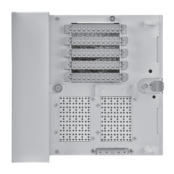
- Page 4 3.8 Complete the PST core removal over the gland. 3.9 The blank plate MUST be used in the empty cable port for UL Listing. 3.10 Attach the cable to the wall according to your company’s practice. 4.0 Terminal Grounding 4.1 Fasten a #6 AWG wire to the ground bar which is located on the front of the unit. Connect other end of ground wire to local ground per company standards. Note: F ailure to properly bond and ground the terminal per N.E.C. or local equivalent codes may render protection arrestors useless. 4.2 Module splicing. Splice per your company practice. 4.3 Splice the feeder cable groups to the corresponding connectorized stubs according to your company’s practice. 4.4 3M Scotchlok Connector or individual connector splicing ™ ™ 4.5 Splice the feeder cable groups to the corresponding connectorized stubs in the IBET terminal according to your company’s practice. 4.6 When all splicing is completed, bundle the groups and secure them with tie wraps into the splice chamber on the left side. 4.7 Close the IBET terminal splice chamber cover and secure with the lockplate bolt. (See 7.02) 5.0 Distribution (House) Wire Termination 5.1 Remove the block from frame. Rotate the block 180°. backward and remount in same frame...
- Page 5 6.0 Running Jumpers 3M Quick Connect System 2810 Block ™ 6.1 Open the feeder pair jumper cap by pushing up on the latch and rotating up. Insert jumper wire ends A (tip) left and B (ring) right into wire openings in the cap, making sure they are inserted all the way to the back of the cap. 6.2 While holding the jumper wires in place, close the cap and press to snap the latch firmly into place. 6.3 Route the jumper wires to the distribution pair through wire loops on the block ends and through vertical and horizontal wireways. Cut jumper wires to appropriate length, leaving at least 5 cm (2 in.) of slack. 6.4 Terminate the jumper wires to the distribution pair by repeating the procedure described in steps 3.1 and 3.2. 6.5 Terminate additional jumper wires by repeating the above procedure. 6.6 To remove jumper wires, open the cap and pull the wires straight out from block. 6.7 Route the wire below the connected cap. 7.0 Installing the Electrical Protectors Note: Use ONLY UL Recognized or Listed protectors in the IBET. 7.1 The 3M Indoor Building Entrance Terminal ™ (IBET) 4588V-QCS uses a standard five pin protector receptacle field. The long pins of the...
-
Page 6: Protective Cover
7.3 To disconnect the distribution wire, pull the protector out to the detents on the long pins to hold it in place. This continues to protect from the feeder cable side. 8.0 Protective Cover 8.1 With the cover closed, the exposed hasp allows for locking when security is required. 9.0 3M Single Pair Test Probe 2827 ™ 9.1 Testing using 3M Single Pair Test Probe 2827 ™ 9.2 Plug the test probe into the cap of the pair being tested, with the black lead to the left and the red lead to the right. 10.0 3M Priority Caps ™ 10.1 Priority Caps are used to designate special purpose circuits and prevent entry of the 3M Single Pair Test Probe. 78-0013-1813-4-A... - Page 7 10.2 To install Priority Caps, place over the jumper cap of the pair to be marked and push it into place. Latching is indicated by an audible snap. 11.0 M ultiple 3M Indoor Building Entrance Terminal (IBET) 4588V-QCS ™ Installation Note: Use this application when the required cable pair capacity exceeds the capacity of a single IBET Terminal. 11.1 The design of the splice chamber and the grooved cable glands make it possible to stack the IBET terminal vertically, up to three of the same cable pair count and within the diameter limits in the chart in 3.01. 11.2 Mounting the IBET terminal Mount the IBET terminal bodies using the cable glands to position them. 21" Assemble the feeder cable strain relief according to Section 3.0 and prepare the feeder cable so that 21" of free conductor length will be in the last IBET terminal. 1" minimum 2.75" minimum 11.3 Place cable glands around the free conductors and position into the IBET terminal. 11.4 Separate the feeder cable pair assigned to each IBET terminal; splice and bond the IBET terminal according to section 4.0.
- Page 8 78-0013-1813-4-A...
- Page 9 78-0013-1813-4-A...
- Page 10 Warranty; Limited Remedy; Limited Liability. This product will be free from defects in material and manufacture for a period of one (1) year from the time of purchase. 3M MAKES NO OTHER WARRANTIES INCLUDING, BUT NOT LIMITED TO, ANY IMPLIED WARRANTY OF MERCHANTABILITY OR FITNESS FOR A PARTICULAR PURPOSE.
Need help?
Do you have a question about the 4588V-QCS Series and is the answer not in the manual?
Questions and answers