Table of Contents
Advertisement
Quick Links
Advertisement
Table of Contents

Related Manuals for Aspira ASPIRCOMFORT V


Summary of Contents for Aspira ASPIRCOMFORT V
-
Page 2: Fundamental Safety Rules
E N G L I S H ASPIRCOMFORT V 1. GENERAL 1.1 INTRODUCTION This manual was prepared with the aim of making the installation and management of your system as simple as possible. By reading and applying the suggestions of this manual, you can achieve the best performance of the purchased product. - Page 3 E N G L I S H ASPIRCOMFORT V • It is forbidden to pull, detach, twist the electrical cables coming out of the device, even if it is disconnected from the electrical power mains. • It is forbidden to insert objects and substances through the air intake and supply grids.
- Page 4 E N G L I S H ASPIRCOMFORT V 1.4 WARNINGS The unit must be installed by qualified and authorised personnel according to the rules in force in the various countries. If installation is not carried out, this could lead to a situation of danger Avoid installing the unit in very damp rooms or where there are large sources of heat.
-
Page 5: Construction Features
E N G L I S H ASPIRCOMFORT V 1.5 CONFORMITY The CE marking (applied on each machine) certifies compliance with the following Community standards: • Machinery Directive 2006/42/EC • Low Voltage Directive 2014/35/EC • Electromagnetic Compatibility Directive 2014/30/EC •... -
Page 6: Description Of Operation
E N G L I S H ASPIRCOMFORT V FANS Brushless fans with electronic motor and modulating control. Very high efficiency and low noise levels. FILTERS ePM1 70/80% filters with low head loss. Easily removable in either horizontal or vertical positioning. -
Page 7: Requirements For Start-Up
E N G L I S H ASPIRCOMFORT V 1.10 STATE OF SUPPLY The supply includes: • recovery unit complete with fans installed inside the unit • polypropylene counter current exchanger pre-inserted inside the unit; • 2 ePm1 class filters pre-inserted inside the unit;... -
Page 8: Installation Conditions
E N G L I S H ASPIRCOMFORT V 2. INSTALLATION 2.1 INSTALLATION CONDITIONS The unit must be installed based on national and local regulations governing the use of electrical devices and based on the following indications: • install the unit inside residential buildings with room temperature between 0°C and 45°C;... -
Page 9: Unit Positioning
E N G L I S H ASPIRCOMFORT V 2.2 UNIT POSITIONING WALL-MOUNTING To mount the unit on the wall, it is necessary to: install the condensation discharge kit on the bottom panel: remove the plugs, insert the internal connection pipe and screw the trap on externally;... -
Page 10: Condensate Discharge Connection
E N G L I S H ASPIRCOMFORT V 2.3 CONDENSATE DISCHARGE CONNECTION Because of the heat recovery system (the exhaust air is cooled by the air supplied into the heat exchanger), the humidity contained in the internal air condenses inside the unit. -
Page 11: Aeraulic Connections
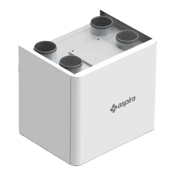
E N G L I S H ASPIRCOMFORT V AERAULIC CONNECTIONS 3.1 AERAULIC ORIENTATIONS The unit has 4 circular male connections of different Ø based on the size: for optimal function. To correctly connect the air ducts, refer to the following diagram and stickers on the unit. -
Page 12: Electrical Connections
E N G L I S H ASPIRCOMFORT V ELECTRICAL CONNECTIONS 4.1 GENERAL - Before starting any operation to perform the electrical connection make sure that the unit is not electrically powered - Perform the necessary electrical connections referring exclusively to the wiring diagram attached to this manual. -
Page 13: Unit Wiring Diagrams
E N G L I S H ASPIRCOMFORT V 4.2 UNIT WIRING DIAGRAMS Room air probe Exhaust Probe Outdoor Air Probe POWER SUPPLY 230/1/50 POST VALVE / COIL CONNECTIONS SET UP BY THE CUSTOMER CHILLER Chiller / Generator activation Dry Contact (hot/cold request... - Page 14 E N G L I S H ASPIRCOMFORT V 4.3 ELECTRICAL CONNECTIONS CH193VMC REMOTE PANEL CONNECTION The board uses a capacitive touch type of remote control to manage all of the functions of the unit and is set up for wall or outdoor 503 box installation;...
- Page 15 E N G L I S H ASPIRCOMFORT V EXTERNAL COIL INSTALLATION 5.1.1 ELECTRIC COILS The unit can feature an electric coil that can be installed as described below. The coil has an internal thermostat that can also be connected to an external thermostat. For details of the electrical connections, follow the instructions provided in the coil manual This directly controls the electric coil through the Chiller contact, on the board;...
-
Page 16: Maintenance
E N G L I S H ASPIRCOMFORT V MAINTENANCE To always guarantee correct and optimal unit operation, it is necessary to periodically perform all of the maintenance activities. 6.1 FILTER CLEANING AND REPLACEMENT To replace the filters, or periodically clean them, do the following: •... -
Page 17: Heat Exchanger Cleaning
E N G L I S H ASPIRCOMFORT V 6.2 HEAT EXCHANGER CLEANING It is advisable to check the status of the heat exchanger every time the filters are cleaned/changed, and clean it if necessary. This must only be done by qualified personnel (installer). - Page 18 E N G L I S H ASPIRCOMFORT V 6.3 GENERAL UNIT CLEANING It is advisable to occasionally check and possibly clean the fans of the condensation discharge and the inside walls of the unit. These activities must only be carried out by qualified personnel (installer).
- Page 19 E N G L I S H ASPIRCOMFORT V ALARMS In case of any problems or failures, take note of any error code appearing on the remote control screen, take note of the model and the serial number of the unit you possess (data provided on the identification plate attached on the side of the unit) and contact the installer.
- Page 20 E N G L I S H ASPIRCOMFORT V 7.2 TABLE OF ALARMS REPORTED ON THE CH193VMC DISPLAY Below is the table of unit operating anomalies reported on the remote display. CODE DESCRIPTION CAUSE SOLUTION VMC: AIR Return Probe Alarm...
- Page 21 ........................................................................................................................................................................................................................................................................................................................................................................................................................................................................................................................................................................................................................................................................................................................................................................................................
- Page 22 ........................................................................................................................................................................................................................................................................................................................................................................................................................................................................................................................................................................................................................................................................................................................................................................................................
- Page 24 FANTINI COSMI S.p.A. Via Dell’Osio, 6 - 20090 Caleppio di Settala, Milan, Italy Tel. +39 02 956821 | Fax +39 02 95307006 E-mail: info@aspira.it | supportotecnico@aspira.it www.aspira.it...
Need help?
Do you have a question about the ASPIRCOMFORT V and is the answer not in the manual?
Questions and answers