Advertisement
Quick Links
V A N T A G E C O N T R O L S . C O M
2168 West Grove Parkway, Suite 300, Pleasant Grove, UT. 84062 USA
Telephone: 801 229-2800 ● Fax: 801 224-0355
Overview
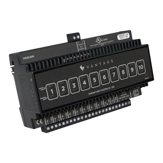
The DIN Contact Input Station WireLink™ model, CIS10-DIN and
RadioLink™ model, STIDER121 feature 10 contact input channels for
receiving Dry-Contact Open/Close states from external devices.
Various types of external switches and sensors are available from
Vantage and other third party manufacturers. These include
magnetic door contact switches, momentary switches, motion
detectors, stress sensors, humidity and temperature sensors,
smoke and carbon monoxide detectors, driveway probes, etc.
Station Specifications
Description
Dimensions, HWD
Weight
Mounting
Number of Contacts
Max. Current from +12V
Station Wiring
configuration
2C, 16AWG / 1.31mm2, twisted, non-
shielded, <30pF per foot. Separate a
Station Bus Specification
minimum of 12" / 30.5cm from other
parallel communication and/or high
Station Equivalent
InFusion
Station Equivalent
RadioLink
Station Bus connections*
LED Indicators
Ambient Operating
Temperature
Ambient Operating
Humidity
CE, UL and CUL Listed
*CAUTION: 36V stations have a
sticker. Any station, not displaying this symbol, should not be
connected to a 36Volt Station Bus.
Software/Firmware
The WireLink and RadioLink models are compatible with InFusion
Design Center software. For new projects it is recommended that
firmware and software be kept to the most current release.
Installation/Mounting
Installation
of
Vantage
products
supervised by a Certified Vantage Installer. There are two methods
of connecting the Station Bus to the Contact Input Relay Station:
1.
Using the Station Bus connection on the removable
screw terminal connectors.
2.
The RadioLink model requires a 15-36VDC, 500mA power
supply.
Connecting Device Requirements
All low voltage connections to each Contact Input are wired to
removable screw terminal connectors. All 10 Contact Inputs are
available on the bottom of the Station. Each Contact Input can be
given custom names in software to facilitate their use in the
installation.
Auxiliary 12Vdc connections are also available on the DIN CIS screw
terminal connectors. There are 4 screw terminal connections
available with a maximum, combined current of 50ma or any single
connection with a maximum of 50ma. The ground for the 12Vdc
connections is any one of the Contact Input ground connections.
The DIN CIS has two sets of removable screw terminal connectors
on the bottom for wiring. Any device that connects to the CIS must
only use the CIS ground for the ground reference.
©Vantage, 1/3/2017 / IS-0584-B
Specification
85.7mm x 157.2mm x 61.9mm
3.38" x 6.19" x 2.44"
201g / 7.09oz
35 mm DIN Rail (EN 50 022: 1977)
10
50mA combined
Daisy-chain/Star/Branch
voltage runs.
0.5W on IC-24 / 0.7W on IC-36
1 Station on RadioLink Systems
24V / 36V Station Bus
Contact State, Program State and
Status
0-35°C / 32-95°F
5-95% non-condensing
Yes
symbol on the Serial Number
should
be
performed
DIN WireLink and RadioLink CIS — MODEL: CIS10-DIN & STIDER121
I N S T A L L A T I O N
DIN WireLink and RadioLink CIS — MODEL: CIS10-DIN & STIDER121
This is often called a "floating" or "isolated" input to the DIN CIS.
This isolation can be provided from several different systems. The
most common are door contacts and motion detectors, providing a
dry contact relay connection to the CIS. Battery powered devices
that are not connected to other equipment can be used with the
DIN CIS. Devices that are powered from the +12Vdc and CIS
ground connections can also be used.
The DIN CIS inputs can accept small voltage levels (0 to 12VDC)
instead of dry contacts as long as the voltage is only referenced to
the CIS's ground. The input will switch the CIS when the voltage
reaches the required level. The logic may be reversed in the
software by changing the polarity from Normally Open to Normally
Closed. A power level of 0.0VDC to 0.5VDC equals a PRESS,
3.0VDC to 12VDC equals a RELEASE. A 2.0VDC power range is
insufficient to toggle an Open/Close state.
Example:
Current CIS State
Open
Closed
WIRE RECOMMENDATION: Contact wire runs should be
limited to 250 feet / 76.2 meters for each wire run, using
a minimum of 20AWG gauge wire. All connections use
4.4 inch pound torque. Stranded wire recommended.
Station Set Up in Software
InFusion: First select the room, then click on Vantage Objects in
the Object Explorer and expand Stations, WireLink or Stations,
RadioLink. From the list of stations double click on the DIN Contact
Input Station to place it in the room. In the Object Editor, name the
station and make sure it is on the correct station bus port. Each
contact is also listed in the Object Editor and may be assigned to a
task and given unique names, Polarity and Hold On Time settings.
Programming Contact Inputs
When
programming,
appropriate tasks or functions available in Design Center, and work
like a button press and release. Select Switch Polarity Normally
Open or Normally Closed and set Switch Hold Time (Default hold
time of 0.00s, is normally used).
Configuration with WireLink Models
When the DIN CIS is first connected to the Station Bus, the Status
LED will blink twice followed by a pause, meaning that the station
is connected correctly but not yet configured. From Design Center,
click in the Serial Number section in the Object Editor and type in
the serial number. Once configured, the Status LED will blink
evenly. The ability to configure a CIS station by pressing any button
on the front of the CIS was removed because it was possible for the
station to send unwanted presses during the configuration stage
causing a station to receive the wrong serial number. An example
or
of this happening is as follows: A CIS could have motion detectors
connected to it and when walking through a project to configure
stations the person walking could inadvertently cause the motion
detectors to send button presses telling the software to configure
the station that was currently highlighted in the Configure Stations
window. This could happen on DIN CIS and Standard CIS stations.
Now Button presses received from dry-contacts are ignored when
on-line configuration is selected.
Configuration with RadioLink*
RadioLink DIN CIS stations need to be configured to associate
which physical station goes with the station in software.
When the station is initially powered-up, the Status LED will blink
three times followed by a pause - this means the station is
powered correctly but not yet on the network. Before uploading
the file to the Vantage system, do the following: From Design
Center, click in the Serial Number section in the Object Editor and
type in the serial number.
The serial number of each station is located on the station. Record
the number for easy reference when programming. The Main
Controller will add to its network and configure all the RadioLink
stations that it has serial numbers for. This may take several
minutes depending on the number of RadioLink stations on the
V A N T A G E I N S T A L L G U I D E S
Input Voltage
Resulting CIS State
< 0.5V
Closed (PRESS)
> 3.0V
Open (RELEASE)
each
Contact
Input
can
trigger
any
page 1 of 2
Advertisement

Related Manuals for LEGRAND VANTAGE CIS10-DIN


Summary of Contents for LEGRAND VANTAGE CIS10-DIN
- Page 1 I N S T A L L A T I O N V A N T A G E C O N T R O L S . C O M V A N T A G E I N S T A L L G U I D E S 2168 West Grove Parkway, Suite 300, Pleasant Grove, UT.
- Page 2 I N S T A L L A T I O N network. The Status LED will blink steadily when a station has been illuminates when the contact input is grounded. The Program State added to the network and configured. LED operates the same as switch LEDs on a keypad station.