Table of Contents
Advertisement
Quick Links
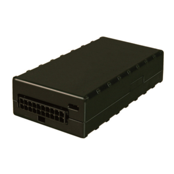
FL18
™
GPS Tracking Device
KIT CONTENTS:
• Tracking Device
• External Antenna
(optional)
• 20-pin I/O cable
MOUNTING THE DEVICE:
• Mount the FL18 under the vehicle's dash, label-
side up, using zip- ties or double-sided tape, in a
location that is clear of any metallic obstructions
from above that might cause interference with GPS
signal reception
MOUNTING THE ANTENNA (WHEN APPLICABLE):
• Mount the antenna with the 3M tape facing
downward, on the front-left side of the dash, near
the vehicle's A-pillar
• Route the COM and GPS wires from the antenna
down to the FL18 and connect them to the
appropriate terminals
MOUNTING THE DRIVER ID READER (WHEN
APPLICABLE):
• Drill a 3/8" hole in the location on the dash where
the driver ID reader will be mounted
• Feed the wires from the driver ID reader through
the 3/8" hole and push the reader in
• Secure the reader from the back side using the
supplied push- washer
CONNECT TO POWER AND GROUND:
• Locate a constant 12v power source and a
suitable chassis ground
• Connect the red wire in the device harness
to 12v power
• Connect the black wire in the device
harness to ground
FL_FL18 - Installation 2017.indd 1
• Garmin FMI Cable
(optional)
• Driver ID Reader
(optional)
• Connectors/Zip Ties
CONNECT THE IGNITION SENSE WIRE:
• Using the vehicle's service manual and a
digital voltmeter, locate a switched 12v
power source (receives power with the
ignition in the 'on' position but does not
receive power in the 'off' or 'acc' positions)
• Connect the white wire in the device
harness to the switched power source
CONNECT THE PTO INPUT (WHEN
APPLICABLE):
• Connect the yellow wire in the device
harness to the PTO trigger's output wire
CONNECT THE DRIVER ID READER
(WHEN APPLICABLE):
• Connect the black wire (pin #16) in the
device harness to the black wire from the
driver ID reader
• Connect the white/blue wire (pin #17) in
the device harness to the gray wire from
the driver ID reader
©2017 Spireon, Inc. All rights reserved.
7/24/17 11:09 AM
Advertisement
Table of Contents

Related Manuals for Spireon FleetLocate FL18


Summary of Contents for Spireon FleetLocate FL18
- Page 1 • Connect the red wire in the device harness to 12v power • Connect the black wire in the device harness to ground ©2017 Spireon, Inc. All rights reserved. FL_FL18 - Installation 2017.indd 1 7/24/17 11:09 AM...
- Page 2 FL18 and the sky. ‘on’ position. appropriate wires. Any metallic obstructions from above will result in interference with GPS reception. ©2017 Spireon, Inc. All rights reserved. FL_FL18 - Installation 2017.indd 2 7/24/17 11:09 AM...
Need help?
Do you have a question about the FleetLocate FL18 and is the answer not in the manual?
Questions and answers