Advertisement
Quick Links
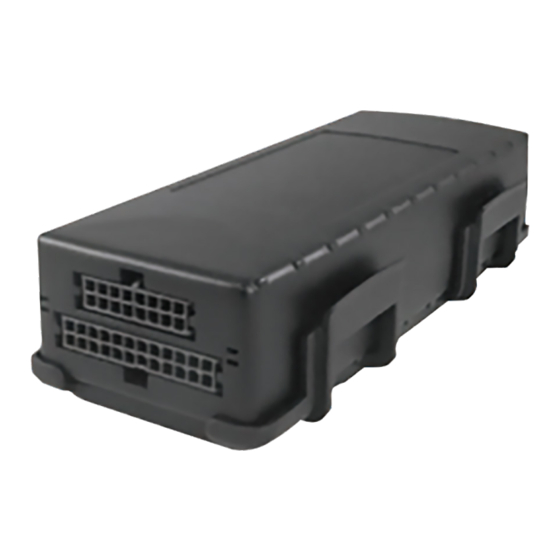
FL1
™
GPS Tracking Device
KIT CONTENTS:
Tracking Device
•
24-pin I/O cable
•
OBDII/Heavy Duty Harness
•
Power Harness
•
Driver ID Reader (optional)
•
Connectors/Zip Ties
•
Mounting Plate
•
Mounting the Device:
Mount the FL1 under the vehicle's dash, label-
•
side up, using zip-ties, double-sided tape, or a
mounting plate in a location that is clear of any
metallic obstructions from above that might cause
interference with GPS signal reception
CONNECT THE POWER, GROUND AND IGNITION
SENSE WIRE:
The ground line (black wire) must be connected to
•
chassis ground.
The power input (red wire) must be connected
•
to a constant (un-switched) +12 VDC or +24 VDC
supply; preferably, connected directly to the vehicle
battery terminal or as close to it as possible. This
connection point should be fuse protected to not
more than 5 Amps.
The ignition input (white wire) must be connected
•
to the vehicle ignition or another appropriate key
operated line, such as ACCESSORY, ensuring that
power to the ignition wire is available only when the
vehicle ignition is on.
Once these three wires are connected, plug the
•
harness into the FL1 device.
NOTE: Please confirm that the device is powered
•
prior to installing the OBDII/JBUS harness and that
the fuse is in the fuse holder.
IMPORTANT NOTE:
The switched power source should read 0v
with the key in the 'off' position and 11-14v in
the 'on' position.
CAUTION:
Use the vehicle's factory service manual
and a digital voltmeter to be sure that
you've located the appropriate wires.
REMEMBER:
For proper operation, there must be an
unobstructed line of sight between the FL1
and the sky. Any metallic obstructions from
above will result in interference with GPS
reception.
©2018 Spireon, Inc. All rights reserved.
Advertisement

Related Manuals for Spireon FleetLocate FL1


Summary of Contents for Spireon FleetLocate FL1
-
Page 1: Mounting The Device
Once these three wires are connected, plug the • harness into the FL1 device. NOTE: Please confirm that the device is powered • prior to installing the OBDII/JBUS harness and that the fuse is in the fuse holder. ©2018 Spireon, Inc. All rights reserved. - Page 2 3 PIN MALE CONNECTOR 3MM PITCH Yellow Negative Output for Door 4 PIN FEMALE CONNECTOR Unlock 3MM PITCH 3 PIN FEMALE CONNECTOR Black Ground 3MM PITCH 2 PIN FEMALE CONNECTOR 12v Constant OPEN WIRES ©2018 Spireon, Inc. All rights reserved.
- Page 3 Connect the white wire to one side of the vehicle’s starter wire (87a) • Connect the long red wire to the other side of the vehicle’s starter wire (30) • Make sure to cut/disconnect the diode between 86 and 85 connectors • ©2018 Spireon, Inc. All rights reserved.
- Page 4 Connect the relay’s long red wire to FL1’s blue wire (30) • Connect the relay’s green wire to ground (86) • DOOR UNLOCK (WHEN APPLICABLE): Yellow Wire is the Unlock Trigger [negative double pulse] • ©2018 Spireon, Inc. All rights reserved.
Need help?
Do you have a question about the FleetLocate FL1 and is the answer not in the manual?
Questions and answers