Table of Contents
Advertisement
- Data Brochure
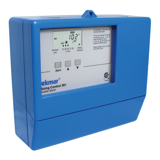
Mixing Control 361
The Mixing Control 361 is designed to control the supply water temperature to a hydronic system in order to provide outdoor reset or
setpoint operation. The control uses a variable speed injection pump to regulate the supply water temperature, while protecting the
boiler against flue gas condensation. The control has a Liquid Crystal Display (LCD) to view system status and operating information.
Additional functions include:
• Quick Setup for easy installation and programming of control
• User comfort adjustment to increase or decrease building
space temperature
• Advanced settings to fine-tune building requirements
• Boiler Control for improved energy savings
• Powered mixing system pump output
Note:
Mixing demand must be
powered with 20 to 260
V (ac) before pumps will
operate or the boiler is
able to fire.
Input
Mixing Demand
Signal
Input
120 V (ac) Power
Supply
Output
Mixing System
Pump
VIEW
° F
MIX
OCC
70 90
Mixing
Terminal
10
30
50
% Out
Unit
Demand
Item
Mixing Control 361
Variable Speed
1
2
3
4
5
6
7
8
Power
Mixing
Sys
Var
Demand
L
N
Pmp N
Pmp N
Output
Variable Speed
Driven Pump
• Optional indoor sensor for room air temperature control
• Test sequence to ensure proper component operation
• Setback input for energy savings
• 120 V (ac) power supply
• CSA C US certified (approved to applicable UL standards)
Advanced
To increase or decrease the
building temperature:
Press the Item , , buttons
Installer
simultaneously for 1 sec. to
enter the ADJUST menu
Use the ,
buttons to
adjust the ROOM setting
Display defaults back to VIEW
menu after 20 sec.
Test
Made in Canada by
tekmar Control Systems Ltd.
tektra 913-01
Power:
Variable Pump:
C
US
Relays:
Demand:
Do not apply power
11 12 13 14 15 16 17
9 10
UnO
Com Boil Mix Com Out Indr
Boiler
Sw
Input
tekmar Timer
Optional
Output
Universal Sensor
Boiler
1 of 20
30% Enable
Return
Boiler Sensor
Supply
10% Enable
Installer Instructions
ROOM - Set to desired room temp.
OUTDR DSGN - Set to coldest (design)
outdoor temp.
Terminal Unit
Set to
High Mass Radiant
1
Low Mass Radiant
2
Fan Coil
3
Convector
4
Radiator
5
Baseboard
6
Refer to brochure for more information
Meets Class B:
Canadian ICES
FCC Part 15
120V + 10% 50/60 Hz 1650 VA
240V (ac) 2.4 A (FLA) 5 A (LRA), fuse T2.5 A
240V (ac) 10 A 1/3 hp
20 to 260 V (ac) 2 VA
Signal wiring must be
rated at least 300V.
Input
Input
Universal Sensor
Included
Included
Copyright © D 361 - 03/09
D 361
03/09
Input
Indoor Sensor
Optional
Input
Outdoor
Sensor Included
Advertisement
Table of Contents

Related Manuals for Tekmar Mixing Control 361


Summary of Contents for Tekmar Mixing Control 361
- Page 1 Mixing Control 361 The Mixing Control 361 is designed to control the supply water temperature to a hydronic system in order to provide outdoor reset or setpoint operation. The control uses a variable speed injection pump to regulate the supply water temperature, while protecting the boiler against flue gas condensation.
-
Page 2: Table Of Contents
How To Use The Data Brochure This brochure is organized into four main sections. They are: 1) Sequence of Operation , 2) Installation , 3) Control Settings , and 4) Troubleshooting . The Sequence of Operation section has three sub-sections. We recommend reading Section A: General Operation of the Sequence of Operation , as this contains important information on the overall operation of the control. -
Page 3: Description Of Display Elements
Display Number Field Item Field Displays the current value of Displays an abbreviated the selected item name of the selected item OUTDR DSGN DIFF VIEW ADJUST ° F Menu Field BOIL TARGET Displays the ° C current menu ROOM WWSD UNOCC INDR Terminal... -
Page 4: Sequence Of Operation
POWERING UP THE CONTROL When the Mixing Control 361 is powered up, the control displays the control type number in the LCD for 2 seconds. Next, the software version is displayed for 2 seconds. Finally, the control enters into the normal operating mode. -
Page 5: Section B: Mixing
EXERCISING The 361 has a built-in exercising function. If a pump has not been operated at least once every 3 days, the control turns on the output for 10 seconds. This minimizes the possibility of a pump seizing during a long period of inactivity. While the control is exercising, the Test LED flashes. - Page 6 CHARACTERIZED HEATING CURVE When used as a mixing reset control, the 361 varies the supply water temperature based on the outdoor air temperature. The control takes into account the type of terminal unit that the system is using. Since different types of terminal units transfer heat to a space using different proportions of radiation, convection and conduction, the supply water temperature must be controlled differently.
- Page 7 High Mass Radiant (1) This type of a hydronic radiant floor is embedded in either a thick concrete or gypsum pour. This heating system has a large thermal mass and is slow acting. Default values: MIX DSGN = 120°F (49°C), MIX MAX = 140°F (60°C), MIX MIN = OFF Low Mass Radiant (2) This type of radiant heating system is either attached to the bottom of a wood sub-floor, suspended in the joist space, or sandwiched between the sub-floor and the surface.
-
Page 8: Section C: Boiler Operation
MIXING MINIMUM (MIX MIN) 210°F The MIX MIN is the lowest temperature that the control is allowed to use (99°C) MIX MAX as a MIX TARGET temperature. During mild conditions, if the 361 cal- Mixing Characterized MIX DSGN culates a MIX TARGET temperature that is below the MIX MIN setting, Heating Curve (88) the MIX TARGET temperature is adjusted to match the MIX MIN set-... - Page 9 Section C2: Boiler Sensor Placement BOILER SENSOR ON THE SUPPLY ( Boiler Sensor DIP switch = Supply ) Boiler supply The boiler sensor can be located on the boiler supply if the 361 is the only control that is sensor operating the boiler.
-
Page 10: Installation
STEP ONE GETTING READY Check the contents of this package. If any of the contents listed are missing or damaged, please contact your wholesaler or tekmar sales representative for assistance. Type 361 includes: One Mixing Control 361, One Outdoor Sensor 070, Two Universal Sensors 082, Data Brochures D 361, D 070, D 001, Application Brochure A 361, Essay E 021. - Page 11 2.4 A. Most small wet rotor circulators are suitable as described in Essay E 021. The 361 has an internal overload pro- tection fuse which is rated at 2.5 A 250 V (ac). Contact your tekmar sales representative for details on the repair procedures if this fuse is blown.
- Page 12 361 to measure the room air temperature. Unoccupied Switch If an external timer (tekmar Timer 032) or switch is used, connect the two wires from the external switch to the UnO Sw and Com terminals (11 and 12). When these two terminals are shorted together, the control registers an unoccupied signal.
- Page 13 Test The Outputs System Pump (Sys Pmp) If a system pump is connected to the Sys Pmp terminal (5), make sure that power to the terminal block is off, and install a jumper between the Power L and the Sys Pmp terminals (3 and 5). Install a second jumper between Power N and N terminals (4 and 6).
-
Page 14: Dip Switch Settings
DIP Switch Settings The DIP Switch settings on the control are very important and should be 30% Enable Advanced Return set to the appropriate settings prior to making any adjustments to the control through the user interface. The DIP switch settings change the Boiler Sensor items that are available to be viewed and / or adjusted in the user Supply... -
Page 15: Control Settings
ADJUST ° F Press and release the Item button to advance to the units adjustment. Use the or button to set the scale to °F or °C. ADJUST To exit the ADJUST menu, press and release the Item button to advance to the ESC item. Then either press button, or leave the buttons alone for 20 seconds. -
Page 16: Adjust Menu
Adjust Menu (1 of 2) Actual Display Description Range Setting ADJUST The desired room air temperature during an ° F 35 to 100°F occupied (Day) period. ROOM (2 to 38°C) ≠ (OUTDR DSGN OFF) ADJUST The desired room air temperature during an °... -
Page 17: Testing And Troubleshooting
Testing the Control The Mixing Control 361 has a built-in test routine which is used to test the main control functions. The 361 continually monitors the sensors, and not testing displays an error message whenever a fault is found. See the following testing pages for a list of the 361’s error messages and possible causes. - Page 18 Troubleshooting When troubleshooting any heating system, it is always a good idea to establish a set routine to follow. By following a consistent routine, many hours of potential headaches can be avoided. Below is an example of a sequence that can be used when diagnosing or troubleshooting problems in a hydronic heating system.
-
Page 19: Error Messages
Error Messages VIEW The control was unable to read a piece of information from its EEPROM. This error can be caused by a noisy power source. The control will load the factory defaults and stop operation until all the settings are verified. -
Page 20: Technical Data
This warranty is in lieu of all other warranties, express or implied, which the Governing Law (being the law of British Columbia) allows parties to contrac- The liability of tekmar under this warranty shall be limited to, at tekmar's sole dis- tually exclude, including, without limitation, warranties of merchantability, cretion: the cost of parts and labor provided by tekmar to repair defects in materials fitness for a particular purpose, durability or description of the product, its...
Need help?
Do you have a question about the Mixing Control 361 and is the answer not in the manual?
Questions and answers