Tekmar tN2 house control 400 Installation And Operation Manual
Hide thumbs
Also See for tN2 house control 400:
- Installation & operation manual (32 pages) ,
- Quick setup manual (12 pages)
Table of Contents
Advertisement
Quick Links
tekmarNet
®
2 House Control 400
Introduction
The tN2 House Control 400 is designed to operate all
of the mechanical equipment in a residential hydronic
heating system, coordinating their operation with network
communication. It can be used in applications ranging
from a single zone of baseboard with an on/off boiler, to
multiple radiant floor zones with a modulating/condensing
boiler. This control regulates one space heating water
temperature through Outdoor Temperature Reset and
Indoor Temperature Feedback. It is capable of controlling
a single on/off, two stage, or modulating boiler, Domestic
Hot Water, setpoint loads, 4 on-board zone valves, and
can expand up to 24 zones in total.
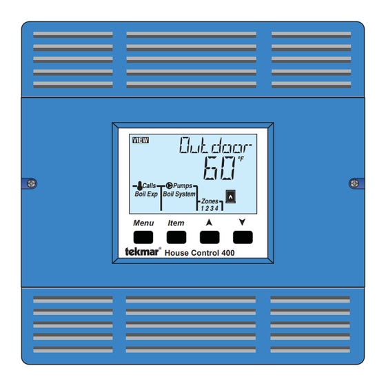
VIEW
Calls
Boil Exp Boil System
Menu
Installation & Operation Manual
Pumps
Zones
1 2 3 4
Item
House Control 400
Features
•
Automatic Boiler Differential
•
Boiler Protection
•
DHW Post Purge
•
DHW Priority (optional)
•
DHW control
•
Exercising
•
For use with tekmarNet®2 thermostats ONLY
•
Four 24 V (ac) powered zone outputs
•
Indoor Temperature Feedback
•
One touch overrides (with optional User Switch)
•
Only requires 2 Wires Per Zone
•
Outdoor Temperature Reset
•
Powered pump outputs
•
Setpoint operation
•
Single on/off, two stage, or modulating boiler
control
•
System Setback (with optional Timer)
•
Warm Weather Shut Down
•
Zone Synchronization
•
tN4 expansion terminals
Benefi ts
•
Energy efficiency through Outdoor Temperature
Reset with Indoor Feedback
•
Indoor Feedback minimizes the water temperature
(increasing energy savings), and the efficiency of
your mechanical equipment through integrated
tekmarNet
®
Thermostats
•
Zone Synchronization reduces equipment cycling
•
Auto Differential - Reduces boiler cycling
•
Compact enclosure for flexible installation
•
Simple zone expansion using Wiring Centers
1 of 32
D 400
09/13
HVAC Systems Replaces: 09/10
© 2013
400_D - 09/13
Advertisement
Table of Contents

Related Manuals for Tekmar tN2 house control 400


Summary of Contents for Tekmar tN2 house control 400
- Page 1 2 House Control 400 09/13 HVAC Systems Replaces: 09/10 Introduction The tN2 House Control 400 is designed to operate all of the mechanical equipment in a residential hydronic heating system, coordinating their operation with network Features communication. It can be used in applications ranging from a single zone of baseboard with an on/off boiler, to •...
-
Page 2: Table Of Contents
It is your responsibility to ensure that this control is safely installed according to all applicable codes and standards. tekmar is not responsible for damages resulting from improper installation and/or maintenance. To avoid serious personal injury and damage to the equipment: •... -
Page 3: Installation
• 14 AWG Solid Wire (Line Voltage Connections) • (4) Wire Nuts • tekmar 009K (24 V (ac) transformer with 4" x 4" junction box) • 18 AWG LVT Solid Wire (Low Voltage Connections) • Cable or Conduit Connectors Power Required -- -- ------- ------- --- -- --- --- --- ------ -- --- --- -- --- ----- --- ----- --- ---- -- --- ---- -- - -- - - -- ----------------------- - -- -- -- - - -- - - - -- - - -- - - - -- - - - -- - - -- - - - -- - - - -- - - - --- - - -- - - - -- - •... -
Page 4: Installation Location
Wiring Center) • Boiler Stage 1 T-T Sizing the Transformer The control requires an external transformer. A tekmar • Each zone valve must be sized for peak load. This can Transformer 009 (or 009K which includes a 4”x 4” electrical... -
Page 5: Control Wiring
The following chart is provided to simplify transformer sizing: Zone Thermostat Load Transformer must exceed: Floating Control Zone Valve Load Action (VA) Load (VA) Total Zone Load Control Wiring Line Voltage Wiring---- -------- ------- --- --- -- --- -- - - ----- -- --- --- -- --- --- -- --- ----- --- ---- - -- - -- --- - - ----------------------- -- - -- -- -- - - -- - - -- - - - -- - - - -- - - -- - - - -- - - - -- - - - -- - - -- - - - -- - - - -- CAUTION: TURN ALL POWER OFF BEFORE PERFORMING ANY WIRING. - Page 6 Outdoor Reset and Indoor Feedback currents. The tekmar Transformer 009 includes a fuse. and operate the boiler to heat the DHW tank or the Setpoint equipment.
-
Page 7: Sensor Wiring
Front Low Voltage Wiring Diagram ------- --- ---- -- -- - --- - -- -- -- - --- - -- ----- --- ----- --- --- ---- - - -- ---- ------- - -- -- -- - - -- - - -- - - - -- - - - -- - - - -- - - -- - - - -- - - - -- - - -- -- - - -- - - -- - - tekmarNet 2 Thermostats ®... - Page 8 Wiring the Outdoor Sensor 070 ------------- - -- -- -- -- -- - --- - -- -- -- -- ----- --- ----- --- ----- ---- - --- -- - - - ------------- - -- -- -- - - -- - - - -- - - -- - - - -- - - - -- - - -- - - - -- - - - -- - - -- - - - -- - - - -- •...
-
Page 9: Testing The Sensor Wiring
If the control display does not turn on, check the Input If a fault is suspected, contact your tekmar sales Power wiring terminals using an electrical multimeter. The representative for assistance. -
Page 10: Max Heat
• If the Boil Type is 1 Stage, the boiler stage 1 relay is Testing the Boiler Stage 1 Contact- -- - -- -- - -- - - - - - -- -- - - - -- - closed for 10 seconds and then opened. Activate the User Test sequence and pause at Step 7 by •... -
Page 11: Applications
Applications Single Boiler, DHW Tank, 4 Boiler Zones A400-1 Description: The House Control 400 operates an On/Off boiler with indirect Domestic Hot Water. The boiler is operated using Outdoor Reset with Indoor Feedback, which supplies the lowest comfortable water temperature to four onboard hydronic zones. - Page 12 Single Boiler, DHW, 8 Boiler Zones A400-2 Description: The House Control 400 operates a modulating boiler with indirect Domestic Hot Water. The House Control 400 operates using Outdoor Reset and Indoor Feedback, which supplies the lowest water temperature to eight hydronic zones.
-
Page 13: User Interface
User Interface Display Item Field Menu Field Displays the name Displays the of the selected item current menu VIEW ADJUST MONITOR Number Field Status Fields Displays the Displays the current current value of status of the control’s the selected item Calls Pumps WWSD Saving... -
Page 14: Navigating The Display
Navigating The Display The 400 uses a simple user interface to accomplish a are used to change the menu, sort through Items, and variety of functions. The four buttons beneath the display adjust each setting as required. Menu Button - -- - -- -- ------ ------ ------- --- -- ---- --- -- ------ -- ------ -- --- --- -- --- ----- --- ----- -- - - --- - - -- -- -- ------------------------ - -- -- - -- - -- - - - -- - - -- - - - -- - - - -- - - - -- - - -- - - - -- - - - -- - - - -- - - - - The menus display in the Menu Field at the top left side of •... -
Page 15: View Menu
View Menu (1 of 1) The View menu items display the current operating temperatures and status information of the system. Item Field Range Description VIEW OUTDOOR SECTION B -76 to 149°F Current outdoor air temperature as measured by the outdoor sensor. The (-60.0 to 65.0°C) outdoor air temperature is shared to all thermostats in the tekmarNet ®... -
Page 16: Adjust Menu
2STG = single two-stage on-off boiler 0-10, Installer 0-10 = 0-10 V (dc) modulating boiler 2STG, 4-20 = 4-20 mA modulating boiler EMS1 = tekmar boiler staging controls 1STG EMS2 = Viessmann modulating boilers with Default = 1STG OpenTherm BOILER DESIGN... - Page 17 Adjust Menu (2 of 3) Item Field Range Access Description Set to MINIMUM MODULATION SECTION E ADJUST The minimum percent modulation of the boiler 0 to 50% Installer burner. Default = 0% Note: This item is only available when the Boiler Type is 0-10 V (dc) or 4-20 mA.
- Page 18 Adjust Menu (3 of 3) Item Field Range Access Description Set to 60 to 200°F ADJUST SETPOINT SECTION D (15.5 to 93.5°C) Installer The minimum boiler target temperature when a Default = 180°F Setpoint Call is present. (82.0°C) ADJUST UNITS °F or °C Installer Default = °F...
-
Page 19: Monitor Menu
Monitor Menu (1 of 1) The Monitor menu items provide information about the system’s operation and performance. To clear any item back to default, press and hold the Up and Down buttons while viewing that item. Item Field Range Description OUTDOOR HIGH MONITOR -76 to 149°F... -
Page 20: Toolbox Menu
Toolbox Menu (1 of 1) The Toolbox Menu is a location for system information and Test functions. If any errors are present on the system, they will be located at the beginning of this menu. Item Field Range Description USER TEST TESTING On or Off Begins the test routine which tests the main control’s functions. -
Page 21: Sequence Of Operation
Sequence of Operation tekmarNet System Section A ® tekmarNet ® is a family of products that use communication • Wiring Centers 313, 314, 315, 316 - Add additional zones to operate the HVAC system in a comfortable and efficient • tN2 and tN4 Thermostats - Add thermostats manner. -
Page 22: Domestic Hot Water Tank Operation
Domestic Hot Water Tank Operation Section C DHW Call - - -- -- -- - -- --------- -- ------- -- ---- --- --- -- --- --- ----- --- ----- --- ----- - --- ----- --- ----- - -- - -- - --- -- -- -- ------------------------ - -- -- -- -- - - -- - - - -- - - - -- - - -- - - - -- - - - -- - - -- - - - -- - - - -- - - -- - - - - A DHW Call is required in order for the control to provide heat to a DHW tank. - Page 23 DHW MODE 3 - DHW in Primary / Secondary no DHW Mode = 3 Priority When a DHW Call is present, the DHW pump and the boiler system pump is operated. Boiler temperature zones can turn on if required. Zone Valve DHW MODE 4 - DHW in Primary / Secondary with ON Or...
-
Page 24: Setpoint Operation
Setpoint Operation Section D A Setpoint Call is required in order for the control to provide When the control receives a Setpoint Call: heat to a setpoint load, such as a spa, pool, or snowmelt • All Boiler zones are turned off. load. - Page 25 It is the amount of time that • To use the tekmar EMS signal operation, the Boil Type the burner must operate before the internal boiler control setting in the Adjust menu must be set to EMS1.
-
Page 26: Pump Operation
In order to decrease temperature swings and increase boiler Auto Differential - - -- ---- -------------- --- --- -- -- - - -- ----------------------- -- - -- efficiency, the Auto Differential feature automatically adjusts Both on-off and modulating boilers are operated with the operating differential of the boiler based on the heating a differential. -
Page 27: Energy Saving Features
Energy Saving Features Section G The “$aving” icon is displayed when energy is being saved. Further Savings! The following features reduce energy consumption. Use a Timer 033 with programmable schedule #1 to gain the WWSD Unoccupied setting. This provides an Network Schedules---- -------- ------- --- --- -- - ----------------------- -- - -- additional WWSD temperature that can be set even lower... -
Page 28: Troubleshooting
Troubleshooting It is recommended to complete all wiring to ensure trouble free operation. Should an error occur, simply follow these steps: 1. Find: If the House Control or tekmarNet ® Thermostat flashes on the screen, it is indicating a problem on the system. 2. -
Page 29: Error Messages
Error Messages (2 of 2) Error Message Description BOILER DEVICE LOST (b:01 TO b:24) Each tekmarNet ® device (thermostat, setpoint control, timer) has an address. The device with this address on the boiler water temperature is no longer reporting back to the 400. The device can be located by either the address, or by going to each device in the building, checking that the LCD is on, and the tekmarNet ®... -
Page 30: Frequently Asked Questions
Frequently Asked Questions Symptom Look For... Corrective Action Control power supply has a 24 V (ac) fuse which if blown, requires Fuse holder replacement. LCD display is off Use electrical meter to measure 24 V (ac) voltage on input power R and C Power to control terminals. -
Page 31: Job Record
Job Record Item Setting Item Setting OUTDOOR DESIGN WWSD UNOCCUPIED BOILER TYPE DHW MODE BOILER DESIGN DHW EXCHANGE BOILER MINIMUM DHW OCCUPIED BOILER MOTOR DHW UNOCCUPIED MINIMUM MODULATION SETPOINT MODULATION DELAY UNITS WWSD OCCUPIED 31 of 32 © 2013 400_D - 09/13... -
Page 32: Technical Data
& other contact informa- tion regarding the appropriate Representative. tekmar Control Systems Ltd., A Watts Water Technologies Company. Head Offi ce: 5100 Silver Star Road, Vernon, B.C. Canada V1B 3K4, 250-545-7749, Fax. 250-545-0650 Web Site: www.tekmarControls.com Product design, software &...
Need help?
Do you have a question about the tN2 house control 400 and is the answer not in the manual?
Questions and answers