Table of Contents
Advertisement
Quick Links
Advertisement
Table of Contents

Related Manuals for Metso PDP Series


Summary of Contents for Metso PDP Series
- Page 1 Model PDP DPU Installation, Preparation and Adjustment 277573 Rev. A1...
- Page 2 Refer to this publication for complete and accurate information that helps you better operate and service Metso Automation MAX Controls equipment. Your comments and suggestions are welcome. Metso Automation MAX Controls 1180 Church Road Lansdale, PA 19446 Attention: Manager, Technical Publications Copyright 1999-2001 by Metso Automation MAX Controls Inc.
-
Page 3: Table Of Contents
CPU Load................................2-6 Takeover Button..............................2-6 Backup DIP Switch Settings ..........................2-6 DPU Keyswitch..............................2-7 CHAPTER 3 ........................3-1 Input/Output Connections............................3-1 Data Highway................................3-1 ACSII Ports ............................... 3-1 Metso Automation MAX Controls • • • • 277573 • • • •... - Page 4 Lockout and Log Options Field......................... 7-5 Serial Ports Field ............................... 7-5 Interaction Page 10..............................7-6 Event Queue Pointer Information........................7-7 Interaction Page 11..............................7-8 Interaction Page 12..............................7-9 Interaction Page 13.............................. 7-10 Metso Automation MAX Controls • • • • 277573 • • • •...
- Page 5 Contents CHAPTER 8 ........................8-1 Alarms and Diagnostics .............................. 8-1 Annunciation of Alarms ............................8-1 Front Panel Numeric LEDs ..........................8-1...
-
Page 6: Preface
Operator' s Guide. You may reload a DPU's configuration from the maxSTATION running maxTOOLS software. Refer to the maxTOOLS online help supplied with the package for configuration installation instructions. Metso Automation MAX Controls • • • • 277573 • • • •... -
Page 7: Chapter 1
A DPU consists of three circuit cards installed in a rack-mounted chassis. The right front chassis panel contains two clockwise and counter-clockwise connectors, two serial ports, 10 terminal blocks, and the DPU keylock. Metso Automation MAX Controls • • • • 277573 • • • •... -
Page 8: Distributed Processing Unit Specifications
If this is not possible, a cable adapter is available (Metso Automation MAX Controls Part Number 081580). This adapter has a metal bracket which mounts to the power strut and a 12-inch connecting cable plugs into J3 or J4 on the back panel. -
Page 9: Mounting Procedures
Peak operating voltage = ±300V Maximum load = 60 mA On resistance = 30 Ohms Off resistance = 1 mOhms (Contact is closed if DPU is online) Circuit Ground Metso Automation MAX Controls • • • • 277573 • • • •... -
Page 10: Chapter 2
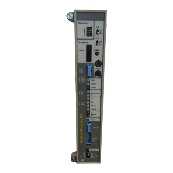
Once the DPU is operational (DPU on DPU Bus), be sure to set the mode switches back to the left. Backup Link Takeover Figure 2-1. Front Panel SIO1 SIO2 Metso Automation MAX Controls • • • • 277573 • • • •... -
Page 11: Data Highway Area
•Two rotary switches to provide the station address; refer to next section. •Two LED displays; refer to "Two LED Displays." There are no internal switches or jumpers to be set during installation. Figure 2-2. Upper Front Panel Area Metso Automation MAX Controls • • • • 277573 • • • •... -
Page 12: Using Rotary Switches To Set Station Address
If an error occurs in the DPU, causing it to fail, these LEDs display an error code. Refer to Chapter 8 for a listing of error codes. IOM Load Metso Automation MAX Controls Factory Service use only. Metso Automation MAX Controls • • • • 277573 • • • •... -
Page 13: Status Section (Leds)
Red = nickel cadmium or lithium battery bad. Yellow = nickel cadmium battery under test. Green = both batteries good. Power Green = DPU powered. Figure 2-3. Status LEDs Metso Automation MAX Controls • • • • 277573 • • • •... -
Page 14: Serial I/O And Dpu Status Section
= no points executing Backup Status LEDs The following two LEDs report backup link status. What the Colors Mean green = Receiving data. green = Transmitting data. Metso Automation MAX Controls • • • • 277573 • • • •... -
Page 15: Reset Button
Common (Shared) is to the left. Separate is to the right. Note: if you are configuring a mixed I/O system using some shared and some separate I/O with a Y-Adapter, select Separate. Metso Automation MAX Controls • • • • 277573 • • • •... -
Page 16: Dpu Keyswitch
In this mode, the DPU executes the functions defined in its point database. Reloads and database changes may or may not be permitted, depending on the DPU configuration as shown on Interaction Page 9. Metso Automation MAX Controls • • • • 277573 • • • •... -
Page 17: Chapter 3
TxD - (RS-422), or TxD (RS-232/423) Receive Data RxD + (RS-422) Receive Data RxD - (RS-422), or RxD (RS-232/423) Request-to-Send RTS (RS-232/423) Clear-to-Send CTS (RS-232/423) Circuit Ground Chassis Ground Metso Automation MAX Controls • • • • 277573 • • • •... -
Page 18: Dpu Battery And Fuse Maintenance
The battery is located in an accessible compartment on the upper right side of the DPU. To access the battery, you must remove the DPU from the rack as described in the following procedure: Metso Automation MAX Controls • • • • 277573 • • • •... -
Page 19: Replacing The Lithium Battery (Battery #1)
DB25 connector. Carefully remove the battery by pulling it straight up. Do not use any metal tools since they could short the battery leads. Additionally, do Metso Automation MAX Controls • • • • 277573 • • • •... -
Page 20: Replacing Dpu Fuses
To change the fuses, follow the same procedure for changing the lithium battery, as described in the previous section, locate and replace the fuses. Metso Automation MAX Controls • • • • 277573 • • • •... -
Page 21: Chapter 5
Manual takeover will occur even if a severe diagnostic alarm or a fatal alarm condition exists in the DPU whose button is pressed. Metso Automation MAX Controls • • • • 277573 • • • •... -
Page 22: Cable Disconnect
DPU, that unit is rendered inactive. If a DPU is not part of a backup pair, a terminator (Part number 081388) must be inserted in place of the cable. Metso Automation MAX Controls • • • • 277573 • • • •... -
Page 23: Chapter 6
When the DPU restarts, it reloads its configuration and erases the flash memory to prevent the possibility of later reloading an out of date configuration. Metso Automation MAX Controls • • • • 277573 • • • •... -
Page 24: Demanding A Cold Startup
Apply pressure to the left of the LEDs to place the force directly in line with the printed circuit card of the module. Metso Automation MAX Controls • • • • 277573 • • • •... -
Page 25: Starting A Backup Pair Of Dpus
Verify that the NiCd battery pack is installed and plugged correctly into P10 connector on the motherboard. Additionally, verify that protective connectors (Part number 081389) are installed in the IOM Metso Automation MAX Controls • • • • 277573 • • • •... - Page 26 Insert the secondary card using the same steps as the primary. Make sure the secondary starts up and begins communicating on the DPU Bus as described above. Return mode switch 4 to the left. Metso Automation MAX Controls • • • • 277573 • • • •...
-
Page 27: Replacing A Dpu In A Backup Pair
Replace the DPU with the new unit, position the new DPU into the top and bottom card guides of the chassis, but DO NOT push the new Metso Automation MAX Controls • • • • 277573 • • • •... - Page 28 Backup Link Timeout. This is done to make sure that there are no higher priority alarms. Metso Automation MAX Controls • • • • 277573 • • • •...
- Page 29 Acknowledge all DPU alarms and make sure they all clear. If the DPU is to be shipped or put in storage, unplug the NiCd battery pack from the P10 connector. Metso Automation MAX Controls • • • • 277573 • • • •...
-
Page 30: Chapter 7
Backup Option DPUs can be paired in a redundant configuration as described in Chapter 5. To configure the backup option, enter Y in the Backup field. Metso Automation MAX Controls • • • • 277573 • • • •... -
Page 31: Digital Input Filter Time Field
Using Interaction Page 9 Display with an Operator Station Use Interaction Page 9 to configure the DPU if a Model 585 Operator Station is being used instead of a maxSTATION. Refer to Figure 7-2. Metso Automation MAX Controls • • • • 277573 • • • •... - Page 32 Figure 7-2. Interaction Page 9, Operator Station Version. The DPU will not become active until Interaction Page 9 is completely configured and the keylock switch is in the Run or Locked position. Metso Automation MAX Controls • • • • 277573 • • • •...
-
Page 33: Startup
Append an A to indicate that loss or failure of one or more of these modules is not a fatal alarm, as would be the default. (Any fatal alarm forces the DPU to Offline mode.) Examples: Metso Automation MAX Controls • • • • 277573 • • • •... -
Page 34: Digital Input Filter Time Field
You may connect asynchronous serial devices to serial ports 1 and 2. The protocols and parameters for these devices are configured here. For additional information about serial links, refer to Publication 277574, DPU Embedded Serial Links User's Guide. Metso Automation MAX Controls • • • • 277573 • • • •... -
Page 35: Interaction
Control Blocks, or ExCEL) is trying to access a module at that address but either no module is present or the module has a communication problem. If the communication problem is intermittent, the address will only be red for 4 Metso Automation MAX Controls • • • • 277573 • • • •... -
Page 36: Event Queue Pointer Information
31 possible high traffic loop stations during normal operation (e.g., 01 XXXXXX YY). The last two digits in the field indicate how many times the queue has wrapped around. Metso Automation MAX Controls • • • • 277573 • • • •... -
Page 37: Interaction
OK TRANSACTIONS Count of successful query/response transactions between the PC and DPU. BUFFER OVERRUNS Count of messages received from PC that were too long to be valid. Metso Automation MAX Controls • • • • 277573 • • • •... -
Page 38: Interaction
PTID the index displayed will be FF. LAST REJECTED ITEM Item number (in hex) of the last database access failure. If the rejected query above does not use an item number field Metso Automation MAX Controls • • • • 277573 • • • •... - Page 39 I/O address Physical I/O bus address of TBxx. This value can be 0-239 (0 = phantom). Module type DIO I/O module type input (IN) or output (OUT). Metso Automation MAX Controls • • • • 277573 • • • • 7-10...
- Page 40 TB24 TB24 TB25 TB25 TB26 TB26 TB27 TB27 TB28 TB28 TB29 TB29 TB30 TB30 TB31 TB31 TB32 TB32 Figure 7-6. Interaction Page 13, Digital Tabular Display. Metso Automation MAX Controls • • • • 277573 • • • • 7-11...
- Page 41 The most likely of those special cases is DC (jabberhalt) combined with one of the following: Metso Automation MAX Controls • • • • 277573 • • • •...
- Page 42 The DPU Bus Card waited for a response from the CP which was never received because the CP re-executed its startup code unexpectedly (jump or return to address 0). Metso Automation MAX Controls • • • • 277573 • • • •...
Need help?
Do you have a question about the PDP Series and is the answer not in the manual?
Questions and answers