Table of Contents
Advertisement
Advertisement
Table of Contents

Related Manuals for Metso Neles Quartz LIMIT SWITCH


Summary of Contents for Metso Neles Quartz LIMIT SWITCH
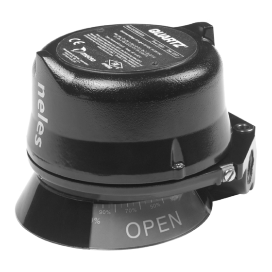
- Page 1 LIMIT SWITCH Neles Quartz Installation, Maintenance and Operating Instructions...
-
Page 2: Table Of Contents
7 QZ 70 en Table of Contents GENERAL............3 Introduction ..........3 Markings ..........3 Specifications......... 3 CE marking ..........5 Recycling and disposal ......5 Safety precautions ......... 5 MOUNTING............5 ADJUSTING............. 6 Touch & Tune™ switch setting ....6 Position transmitter calibration.... -
Page 3: General
8 to 125 VD C/24-125 V AC ❑ CE and EX marks Inrush Current: 2.0 A at 125 V AC/V DC (max) ❑ Metso logo Continuous Current: 0.3 A at 125 V AC/V DC Minimum On Current: 2.0 mA Specifications Current Leakage: Less than 0.25 mA... - Page 4 7 QZ 70 en Intrinsically Safe Inductive Proximity Switches 6.5 V at 100 mA Namur Sensor Dual Module (44) Contact Tungsten Outputs: 2 Namur Sensors (DIN 19234) Mechanical Micro Switches Current Ratings: Silver contacts (V) Target Present Current <1.0 mA (LED = OFF) Electrical ratings: 10.0 A / 125/250 V AC Target Absent Current...
-
Page 5: Ce Marking
7 QZ 70 en Temperature Range: -40 ºC to 82 ºC CAUTION: ID/IO Codes: ID = A; IO = 4; ID1 = 7; ID2 = E To prevent ignition of hazardous atmospheres, Default Address: replace cover before energizing the electrical circuits. Bit Assignment: Inputs Outputs... -
Page 6: Adjusting
7 QZ 70 en ADJUSTING green LEDs will be illuminated during the actuation period. The red LED is off in the “Closed” position and Touch & Tune™ switch setting the green LED is off in the “Open” position. If the optional green "Closed"... - Page 7 7 QZ 70 en II. For Normally Closed Function, Fig. 7 1. With the valve in the closed position, set both cams so that the metal activation strips are aligned with each other and set in the middle of the sensor tar- gets.
- Page 8 7 QZ 70 en Type 44 I Valve Closed to Open in counter-clockwise rotation, Fig. 4 TOP SWITCH 1. With the valve in the "Closed" position, set the bot- tom cam so that the metal activation strip is cen- tered on the bottom sensor target and the top cam BOTTOM SWITCH is 180°...
-
Page 9: Position Transmitter Calibration
7 QZ 70 en 6. Operate actuator to the desired "100 %" position. 7. Adjust the screw on the span trimpot for a 20 mA output. Zero and Span adjustments are non interac- tive. Fig. 12 Cams set for Normally Open function Valve Closed to Open in clockwise rotation, Fig. -
Page 10: Bench Test Procedure
7 QZ 70 en Bench test procedure 3.3.8 Types 96, 97 To Bench Test AS-Interface Module: Use 24 V DC 3.3.1 Type 33 power supply across ASI + and ASI -. No series resistor Use StoneL Light Read Tester. Or use a 24 V DC or 120 V needed. -
Page 11: Dimensions
7 QZ 70 en DIMENSIONS SEE NOTE 2 SEE NOTE 1 6.8 (2) NOTES: 1) COVER HEIGHTS MAY VARY ON DIFFERENT MODELS. - UNIT HEIGHT WITH SHORT COVER = 102 mm 45° COVER REMOVAL CLEARANCE = 143 mm - UNIT HEIGHT WITH MEDIUM COVER = 123 mm COVER REMOVAL CLEARANCE = 184 mm - UNIT HEIGHT WITH TALL COVER = 155 mm COVER REMOVAL CLEARANCE = 241 mm... -
Page 12: Wiring Diagrams
7 QZ 70 en WIRING DIAGRAMS Inductive Proximity Sensors 5.1.1 Type 33 SOL1 SOL 2 SOL PWR 1 SOL PWR 2 TOP SW NO TOP SW C BTM SW C BTM SW NO Note: Models with 3 conduit entries have an additional 2 pole terminal block. -
Page 13: Intrinsically Safe Inductive Proximity Switches
7 QZ 70 en Intrinsically Safe Inductive Proximity Switches 5.2.1 Type 44 SOL1 SOL 2 SOL PWR 1 SOL PWR 2 TOP SW + TOP SW - BTM SW + BTM SW - Note: Models with 3 conduit entries have an additional 2 pole terminal block. -
Page 14: Reed Type Proximity Switches
7 QZ 70 en Reed Type Proximity Switches 5.3.1 Types P and L 2 SPST Switches 4 SPST Switches SPARE 1 SPARE 2 SWITCH SWITCH SECOND BOTTOM SWITCH SWITCH THIRD SWITCH SPARE1 BOTTOM SWITCH SPARE 2 SPARE 3 SPARE 4 5.3.2 Types G, H and S 2 SPDT Switches... -
Page 15: Valve Control Terminals (Vct)
7 QZ 70 en 6 SPDT Switches SPARE THIRD SPARE SWITCH SPARE SECOND BOTTOM SWITCH SWITCH FIFTH SWITCH SWITCH SPARE FOURTH SPARE SWITCH SPARE 5.4.2 Type 14 TOP NC1 TOP NO1 TOP C1 TOP SWITCH TOP C2 (Individual Elements Actuate with Common Plunger) TOP NO2 TOP NC2... -
Page 16: Position Transmitters
7 QZ 70 en 5.5.2 Type 96 ASI + ASI - AUX IN + AUX IN1 - AUX IN2 - 3 wire RTN OUT 2 + Solenoid valve* OUT 2 - OUT 1 + Solenoid valve* OUT 1 + * Solenoid valves not supplied with unit 5.5.3 Type 97... - Page 17 7 QZ 70 en Transmitter with SPDT Switches TRANS + TRANSMITTER TRANS - TOP SWITCH BOTTOM SWITCH SPARE SPARE SPARE SPARE SPARE SPARE Transmitter with Solid State Switches TRANS + TRANSMITTER TRANS - TOP SWITCH BOTTOM SWITCH SPARE SPARE SPARE SPARE SPARE SPARE...
-
Page 18: Type Code
7 QZ 70 en TYPE CODE Limit switch, Neles Quartz PRODUCT GROUP SWITCH TYPE Neles Quartz, Limit switch with mechanical or proximity switches No switches. or position transmitter. Applicable to 2. sign "5" or "7" ATEX certification: Inductive Proximity Switches ATEX II 2 G c T5 Ex d IIC T5 Ta = -40 °C to +80 °C IP67 Temperature range -40 ºC to +80 °C / -40 ºF to +176 °F . - Page 19 7 QZ 70 en...
- Page 20 7 QZ 70 en Metso Automation Inc. Europe, Levytie 6, P.O. Box 310, 00811 Helsinki, Finland. Tel. +358 20 483 150. Fax +358 20 483 151 North America, 44 Bowditch Drive, P.O. Box 8044, Shrewsbury, MA 01545, USA. Tel. +1 508 852 0200. Fax +1 508 852 8172 Latin America, Av.
Need help?
Do you have a question about the Neles Quartz LIMIT SWITCH and is the answer not in the manual?
Questions and answers