Table of Contents
Advertisement
Quick Links
E87010-A0164-T003-A6-LCN0
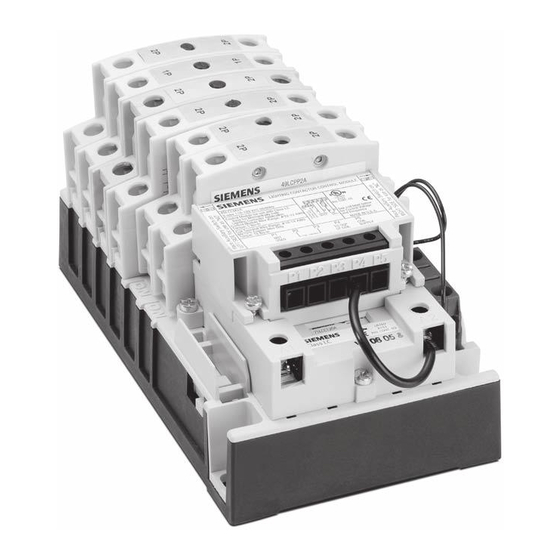
Class LC Electrically Held Lighting Contactor
(Convertible to Mechanically Held)
Catalog numbers LCE00C*
Page 1 of 6
WARNING
Hazardous voltage
Can cause death or serious injury.
Disconnect main power and control voltages before
installation or maintenance on the equipment.
Electrically Held (Standard)
Power Pole Modules
Power pole modules are available in either single pole
(49LCPP1A) or double pole (49LCPP2A) versions.
Main Base
The base of the lighting contactor has provisions to
accept up to six power pole modules for a total of
twelve power poles. A combination of normally open
(N.O.) and normally closed (N.C.) contacts may be
assembled but with a maximum of eight N.C. contacts.
Control Module Kits
Conversion from an electrically held to a mechanically held
contactor can be accomplished with a control module kit.
Kits are available for both 2-wire and 3-wire control in a
variety of control voltages. The control module is available
up to 277V maximum. For control voltage greater than
277V, use a control transformer. Refer to Replacement
Parts and Accessories for catalog numbers. Instruction
and wiring diagrams can be found in the control module
instruction sheets.
Mechanically Held (Optional)
Assembly
Positions 1 through 4 on the base can be
configured to either normally open (N.O.) or
normally closed (N.C.) while positions 5 and 6
can only be configured as normally open (N.O.).
Each position can accept one power pole module.
Each power pole module can consist of either a
single or double power pole.
Instruction sheet
usa.siemens.com/controls
THESE INSTRUCTIONS DO NOT PURPORT TO COVER ALL DETAILS OR VARIATIONS IN EQUIPMENT, NOR
TO PROVIDE FOR EVERY POSSIBLE CONTINGENCY TO BE MET IN CONNECTION WITH INSTALLATION
OPERATION OR MAINTENANCE. SHOULD FURTHER INFORMATION BE DESIRED OR SHOULD PARTICULAR
PROBLEMS ARISE WHICH ARE NOT COVERED SUFFICIENTLY FOR THE PURCHASER'S PURPOSES, THE
MATTER SHOULD BE DEFERRED TO THE LOCAL SIEMENS SALES OFFICE. THE CONTENTS OF THIS INSTRUCTION
MANUAL SHALL NOT BECOME PART OF OR MODIFY ANY PRIOR OR EXISTING AGREEMENT, COMMITMENT
OR RELATIONSHIP. THE SALES CONTRACT CONTAINS THE ENTIRE OBLIGATION OF SIEMENS. THE WARRANTY
CONTAINED IN THE CONTRACT BETWEEN PARTIES IS THE SOLE WARRANTY OF SIEMENS. ANY STATEMENTS
CONTAINED HEREIN DO NOT CREATE NEW WARRANTIES OR MODIFY THE EXISTING WARRANTY.
Pos. 2
Position 1
Pos. 3
IMPORTANT
Auxiliary Contact
The auxiliary contact blocks are
available in either single pole
(49LCAC1PA) or double pole
(49LCAC2PA) versions. Auxiliary
contacts can be installed on either
side of the base. When installed on
the RIGHT side, the auxiliary contact
functions as a N.C. contact. When
installed on the LEFT side, the auxiliary
contact functions as a N.O. contact.
Mounting
Contactor must be mounted in the vertical
position on a sturdy support.
Pos. 4
Pos. 5
Pos. 6
August, 2012
Torque
10 - 15 lb-in
Advertisement
Table of Contents

Subscribe to Our Youtube Channel
Related Manuals for Siemens LCE00C Series


Summary of Contents for Siemens LCE00C Series
- Page 1 PROBLEMS ARISE WHICH ARE NOT COVERED SUFFICIENTLY FOR THE PURCHASER’S PURPOSES, THE installation or maintenance on the equipment. MATTER SHOULD BE DEFERRED TO THE LOCAL SIEMENS SALES OFFICE. THE CONTENTS OF THIS INSTRUCTION MANUAL SHALL NOT BECOME PART OF OR MODIFY ANY PRIOR OR EXISTING AGREEMENT, COMMITMENT OR RELATIONSHIP.
- Page 2 Snap opposite end in place. N.O. N.F. Auxiliary Contact Block Removal Slide flat screwdriver into clip of auxiliary contact module and lift. Siemens Industry, Inc. A5E31166555A-001...
- Page 3 Page 3 of 6 Coil Replacement for Electrically Held Contactors Step 1: Remove the coil cover. Step 2: Remove coil assembly. Step 3: Replace with new coil. Step 4: Reinstall coil assembly and cover. Torque 7 - 12 lb-in Siemens Industry, Inc. A5E31166555A-001...
- Page 4 Step 2: Remove all wires from the control module and remove the coil cover Step 3: Remove coil assembly along with the control module. Step 5: Replace with new coil. Step 4: Replace with new coil. Siemens Industry, Inc. A5E31166555A-001...
- Page 5 3. When coil and line voltages are same, the control voltage may be derived from the line for supply. 4. Ground lug kit number 49D11960001 meets CSA standard 22.2 no. 14-1973 and is rated for 1 conductor 2-14 AWG AL/CU wire. Siemens Industry, Inc. A5E31166555A-001...
- Page 6 ©2013 Siemens Industry, Inc. 1-800-241-4453 info.us@siemens.com All product designations may be trademarks or product names of Siemens AG or supplier companies whose use by third parties for their own purposes could violate usa.siemens.com/controls the rights of the owners.
Need help?
Do you have a question about the LCE00C Series and is the answer not in the manual?
Questions and answers