Siemens SITRANS LVL200E Operating Instructions Manual
Vibrating switches
Hide thumbs
Also See for SITRANS LVL200E:
- Instruction manual (40 pages) ,
- Operating instructions manual (44 pages) ,
- Operating instructions manual (16 pages)
Table of Contents
Advertisement
Quick Links
Advertisement
Table of Contents

Subscribe to Our Youtube Channel
Related Manuals for Siemens SITRANS LVL200E


Summary of Contents for Siemens SITRANS LVL200E
- Page 1 Vibrating Switches SITRANS LVL200E NAMUR Operating Instructions • 11/2015...
- Page 2 SITRANS LVL200E - Operating Instructions *7ML19985KY01*...
-
Page 3: Table Of Contents
Function chart ........................ 22 7 Maintenance and fault rectification Maintenance ........................24 Rectify faults ........................24 Exchanging the electronics .................... 25 Instrument repair ......................25 Dismount Dismounting steps......................26 Disposal ......................... 26 Supplement Technical data ........................ 27 Dimensions ........................34 *7ML19985KY01* SITRANS LVL200E - Operating Instructions... - Page 4 Safety instructions for Ex areas Take note of the Ex specific safety instructions for Ex applications. These instructions are attached as documents to each instrument with Ex approval and are part of the operating instructions manual. Editing status: 2015-11-10 SITRANS LVL200E - Operating Instructions *7ML19985KY01*...
-
Page 5: About This Document
This arrow indicates a single action. Sequence of actions Numbers set in front indicate successive steps in a procedure. Battery disposal This symbol indicates special information about the disposal of bat- teries and accumulators. *7ML19985KY01* SITRANS LVL200E - Operating Instructions... -
Page 6: For Your Safety
During work on and with the device the required personal protective equipment must always be worn. Appropriate use The SITRANS LVL200E is a sensor for point level detection. You can find detailed information about the area of application in chapter "Product description". Operational reliability is ensured only if the instrument is properly used according to the specifications in the operating instructions manual as well as possible supplementary instructions. -
Page 7: Safety Label On The Instrument
SIL conformity SITRANS LVL200E fulfills the requirements to functional safety ac- cording to IEC 61508/IEC 61511. You find further information in the Safety Manual "SITRANS LVL200". Safety instructions for Ex areas Please note the Ex-specific safety information for installation and op- eration in Ex areas. These safety instructions are part of the operating instructions manual and come with the Ex-approved instruments. *7ML19985KY01* SITRANS LVL200E - Operating Instructions... -
Page 8: Product Description
SITRANS LVL200E point level switch • Documentation – This operating instructions manual – Safety Manual "Functional safety (SIL)" (optional) – Ex-specific "Safety instructions" (with Ex versions) – If necessary, further certificates The SITRANS LVL200E consists of the components: Constituent parts • Housing lid • Housing with electronics •... -
Page 9: Principle Of Operation
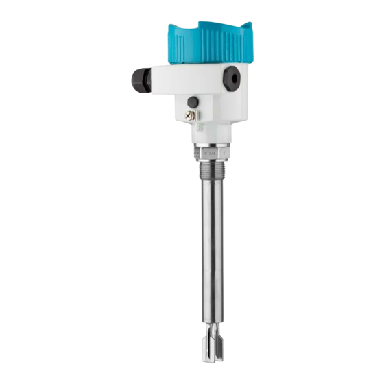
Principle of operation Application area SITRANS LVL200E is a point level sensor with tuning fork for point level detection. It is designed for industrial use in all areas of process technology and can be used in liquids. Typical applications are overfill and dry run protection. The small tuning fork allows use in all kinds of tanks and vessels. Thanks to its simple and rugged measuring system, SITRANS LVL200E is virtually unaffected by the chemical and physical properties of the liquid. -
Page 10: Storage And Transport
For connecting the sensors with a separator to voltage supply or sig- Plug connector nal processing, the sensors are also available with plug connectors. The following plug connectors are available: • M12 x 1 • ISO 4400 SITRANS LVL200E - Operating Instructions *7ML19985KY01*... - Page 11 • Harting HAN 7D • Harting HAN 8D • Amphenol-Tuchel *7ML19985KY01* SITRANS LVL200E - Operating Instructions...
-
Page 12: Mounting
You can find the specifications in chapter "Technical data" and on the nameplate. Switching point In general, SITRANS LVL200E can be installed in any position. The instrument only has to be mounted in such a way that the tuning fork is at the height of the desired switching point. - Page 13 Switching point with higher density Switching point approx. 27 mm (1.06 in) Fig. 3: Horizontal mounting Switching point Fig. 4: Horizontal installation (recommended mounting position, particularly for adhesive products) Switching point Marking with screwed version, facing up In the case of flange versions, the fork is aligned as follows. *7ML19985KY01* SITRANS LVL200E - Operating Instructions...
- Page 14 Use the recommended cables (see chapter "Connecting to power supply") and tighten the cable gland. You can give your SITRANS LVL200E additional protection against moisture penetration by leading the connection cable downward in front of the cable entry. Rain and condensation water can thus drain off. This applies mainly to outdoor mounting as well as installation in...
-
Page 15: Mounting Instructions
Mounting instructions Welding socket SITRANS LVL200E has a defined thread starting point. This means that every SITRANS LVL200E is in the same fork position after being screwed in. Remove therefore the supplied seal from the thread of SITRANS LVL200E. This seal is not required when using a welded socket with O-ring in front. - Page 16 This applies particularly to instrument types with long extension tube. Fig. 8: Inflowing medium Product flow To make sure the tuning fork of SITRANS LVL200E generates as little resistance as possible to product flow, mount the sensor so that the surfaces are parallel to the product movement. SITRANS LVL200E - Operating Instructions *7ML19985KY01*...
- Page 17 For this reason, do not use an overly long extension tube for SITRANS LVL200E, but check if you can mount a short level switch on the side of the vessel in horizontal position.
-
Page 18: Connecting To Power Supply
2. Loosen compression nut of the cable entry gland 3. Remove approx. 10 cm (4 in) of the cable mantle, strip approx. 1 cm (0.4 in) of insulation from the ends of the individual wires SITRANS LVL200E - Operating Instructions *7ML19985KY01*... -
Page 19: Wiring Plan, Single Chamber Housing
Fig. 10: Electronics and terminal compartment, single chamber housing Control lamp DIL switch for characteristics reversal DIL switch for sensitivity adjustment Ground terminal 5 EMC filter element Simulation key Connection terminals Wiring plan For connection of the amplifier according to NAMUR (IEC 60947-5-6, EN 50227). You can find further information in the "Technical data". *7ML19985KY01* SITRANS LVL200E - Operating Instructions... - Page 20 Fig. 11: Wiring plan, single chamber housing SITRANS LVL200E - Operating Instructions *7ML19985KY01*...
-
Page 21: Setup
DIL switch for sensitivity adjustment (3) • Simulation key (4) Note: Always immerse the tuning fork of SITRANS LVL200E in a liquid to test its function. Do not test the function of SITRANS LVL200E with your hand. This can damage the sensor. Adjustment elements Fig. -
Page 22: Function Chart
The following chart provides an overview of the switching conditions depending on the set mode and the level. Note: The mode setting on the NAMUR amplifier must be selected in such a way that the switching output takes on safe state in case of failure (I ≤ 0.6 mA). SITRANS LVL200E - Operating Instructions *7ML19985KY01*... - Page 23 Level Signal current - Control lamp Sensor Falling characteris- ≥ 2.6 mA tics max. Falling characteris- ≤ 0.6 mA tics max. Rising characteris- ≥ 2.6 mA tics min. Rising characteris- ≤ 0.6 mA tics min. Fault ≤ 0.6 mA flashes red *7ML19985KY01* SITRANS LVL200E - Operating Instructions...
-
Page 24: Maintenance And Fault Rectification
Exchange the instrument or send it in for repair Reaction after fault recti- Depending on the reason for the fault and the measures taken, the fication steps described in chapter "Set up" may have to be carried out again. SITRANS LVL200E - Operating Instructions *7ML19985KY01*... -
Page 25: Exchanging The Electronics
Keep in mind that enamelled instrument versions need special electronics modules. These electronics modules are called SW60E or SW60E1. Instrument repair If it is necessary to repair the instrument, please contact Siemens Milltronics Process Instruments Inc. You find the locations on our homepage "www.siemens.com/processautomation". *7ML19985KY01* SITRANS LVL200E - Operating Instructions... -
Page 26: Dismount
WEEE directive. Correct disposal avoids negative effects on humans and the environ- ment and ensures recycling of useful raw materials. Materials: see chapter "Technical data" If you have no way to dispose of the old instrument properly, please contact us concerning return and disposal. SITRANS LVL200E - Operating Instructions *7ML19985KY01*... -
Page 27: Supplement
Ʋ 316L, ECTFE coated 80 … 3000 mm (3.15 … 118.1 in) Ʋ 316L, PFA coated 80 … 4000 mm (3.15 … 157.48 in) Tube diameter ø 21.3 mm (0.839 in) or gas-tight leadthrough *7ML19985KY01* SITRANS LVL200E - Operating Instructions... - Page 28 NAMUR processing system according to IEC 60947-5-6 (EN 50227/DIN 19234) Modes (NAMUR output adjustable to falling or rising characteristics) Ʋ Min. rising characteristic curve (High current when immersed) Ʋ Max. falling characteristics (Low current when immersed) SITRANS LVL200E - Operating Instructions *7ML19985KY01*...
- Page 29 (482 °F) (122 °F) (32 °F) (212 °F) (302 °F) (392 °F) Fig. 22: Influence of the process temperature on the switching point Shifting of the switching point in mm (in) Process temperature in °C (°F) Switching point at reference conditions (notch) Tuning fork *7ML19985KY01* SITRANS LVL200E - Operating Instructions...
- Page 30 Shifting of the switching point in mm (in) Process pressure in bar (psig) Switching point at reference conditions (notch) Tuning fork Repeatability 0.1 mm (0.004 in) Hysteresis approx. 2 mm (0.08 in) with vertical installation Switching delay approx. 500 ms (on/off) Measuring frequency approx. 1200 Hz SITRANS LVL200E - Operating Instructions *7ML19985KY01*...
- Page 31 100 bar/10000 kPa (1450 psig) at a maximum process temperature of +50 °C (+122 °F) (only with threaded versions). Process temperature (thread or flange temperature) Ʋ SITRANS LVL200E of 316L/Alloy C22 -50 … +150 °C (-58 … +302 °F) (2.4602) Process temperature (thread or flange temperature) with temperature adapter (option) Ʋ...
- Page 32 (0.018 … 0.09 lbs/in³) by switching over Vibration resistance Ʋ Instrument housing 1 g at 5 … 200 Hz according to EN 60068-2-6 (vibration with resonance) Ʋ Sensor 1 g with 5 … 200 Hz according EN 60068-2-6 (vibration at resonance) with sensor length up to 50 cm (19.69 in) With a sensor length > 50 cm (19.69 in) you have to fix the extension tube with a suitable support. See mounting instructions. SITRANS LVL200E - Operating Instructions *7ML19985KY01*...
- Page 33 Overvoltage category Protection class Approvals Depending on the version, instruments with approvals can have different technical data. For these instruments, please note the corresponding approval documents. They are included in the scope of delivery. Depending on the version M12 x 1, according to ISO 4400, Harting, 7/8" FF. *7ML19985KY01* SITRANS LVL200E - Operating Instructions...
-
Page 34: Dimensions
~ 59 mm ~ 116 mm (4 ") ") ø 80 mm ø 84 mm (3 ") ") M20x1,5/ M20x1,5 M20x1,5/ ½ NPT ½ NPT Fig. 28: Housing versions Aluminium housing Stainless steel housing, electropolished SITRANS LVL200E - Operating Instructions *7ML19985KY01*... - Page 35 41 (G1A, 1"NPT) "NPT G1A, 1"NPT ø 21,3 mm (0.84") ø 33,7 mm (1.33") Fig. 29: SITRANS LVL200E Thread Clamp Cone DN 25 Slotted nut DN 40 Flange Tuchenhagen Varivent Sensor length, see chapter "Technical data" *7ML19985KY01* SITRANS LVL200E - Operating Instructions...
- Page 36 SITRANS LVL200E, options Fig. 30: Options Gas-tight leadthrough Temperature adapter SITRANS LVL200E - Operating Instructions *7ML19985KY01*...
- Page 37 Trademark All the brands as well as trade and company names used are property of their lawful proprietor/ originator. *7ML19985KY01* SITRANS LVL200E - Operating Instructions...
- Page 38 Notes SITRANS LVL200E - Operating Instructions *7ML19985KY01*...
- Page 39 Notes *7ML19985KY01* SITRANS LVL200E - Operating Instructions...
- Page 40 For more information www.siemens.com/level www.siemens.com/weighing Siemens Canada Limited Subject to change without prior notice PD PA PI LW *7ML19985KY01* Rev. 14.0 1954 Technology Drive P.O. Box 4225 © Siemens AG 2015 Peterborough, ON K9J 7B1, Canada email: techpubs.smpi@siemens.com Printed in Canada www.siemens.com/processautomation...
Need help?
Do you have a question about the SITRANS LVL200E and is the answer not in the manual?
Questions and answers