Table of Contents
Advertisement
www.braunlift.com
®
"Providing Access to the World"
International Corporate Hdqrs: P.O. Box 310
1-800-THE LIFT
®
(574) 946-6153
34275
October
2007
Service Manual for:
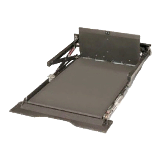
Under-Vehicle Lift
Public Use Wheelchair Lifts
Series
DOT — Public Use Lift
DOT — Public Use Lift
"DOT — Public Use Lift" verifies that this platform lift meets the
"public use lift" requirements of FMVSS No. 403. This lift may be
installed on all vehicles appropriate for the size and weight of the
lift, but must be installed on buses, school buses, and multi-
purpose passenger vehicles other than motor homes with a gross
vehicle weight rating (GVWR) that exceeds 4,536 kg (10,000 lb).
®
®
Winamac, IN 46996 USA
FAX: (574) 946-4670
®
01
01
Read manual
before installing
or servicing lift.
Failure to do so
may result in
serious bodily
injury and/or
property damage.
W A R N I N G
Advertisement
Table of Contents

Related Manuals for Braun UVL 01 Series


Summary of Contents for Braun UVL 01 Series
- Page 1 Service Manual for: ® Under-Vehicle Lift Public Use Wheelchair Lifts Series DOT — Public Use Lift DOT — Public Use Lift “DOT — Public Use Lift” verifies that this platform lift meets the “public use lift” requirements of FMVSS No. 403. This lift may be installed on all vehicles appropriate for the size and weight of the lift, but must be installed on buses, school buses, and multi- purpose passenger vehicles other than motor homes with a gross...
- Page 2 The warranty cards must be processed to activate the warranty. Two Braun Serial No./Series No. identification tags (shown below) are posted on the lift. One I.D. tag is posted on the left platform side plate (outboard end). A second I.D. tag is located on the base of the pump module.
-
Page 3: Table Of Contents
Contents Troubleshooting and Maintenance Lift Terminology ............2 Switch and Sensor Locations ........3 Certification Checklist Diagnostic Procedures ..4 Adjustments and Calibration ........5 LCD Diagnostic Codes ..........6 Floor Level and Inner Roll Stop Adjustments ..7-11 Lubrication Diagram ........... 12 Maintenance and Lubrication Schedule .... -
Page 4: Lift Terminology
Lift Terminology Hydraulic Platform Cable-activated Cylinders Manual Release System Hand-Held Attendant's Control Box Inner Roll Stop Rolling Horizontal Arms Shield Handrail with Belt Outer Barrier Actuator Torque Tube Lifting Two-Stage Arms Outer Barrier Inboard Right Left Outboard Page 2... -
Page 5: Switch And Sensor Locations
Switch and Sensor Locations Full Out Cam Full Out 75776CN Limit Switch Lift Out Cam Lift Out 73950A 73775 Limit Switch Pressure 73950A Transducer 30426 Floor Level Below Stow Limit Switch Limit Switch 73950A 73950A Floor Level Below Stow 73712 73712 Switch 0 Limit Switch... -
Page 6: Certification Checklist Diagnostic Procedures
Platform Lift Installations in Motor Vehicles (49 CFR the referenced procedures to correct the problem 571.404). or contact a Braun Corporation Product Support representative at 1-800-THE LIFT ® • Vehicle movement is prevented unless the lift door is closed, ensuring the lift is stowed. -
Page 7: Adjustments And Calibration
Adjustments and Calibration Adjustment Procedures roller is horizontal. Release and push the manual cable in fully. Ensure platform is locked by moving the plat- Lift Out Switch: The Lift Out Switch stops inward form in and out until chain release assembly engages travel of the carriage/platform during Stow function chain. -
Page 8: Lcd Diagnostic Codes
Repeat the harness diagnostic procedure. If an incorrect value is still present after check- ing the harness and connections, contact The Braun Corporation Product Support Lift_Out Floor_SW ® ® Department at 1-800-THE-LIFT... -
Page 9: Floor Level And Inner Roll Stop Adjustments
Floor Level and Inner Roll Stop Adjustments Achieving proper floor level positioning of the plat- Ensure the lift is positioned and secured as speci- fied on Quick Reference Installation Sheet (sup- form and inner roll stop requires a combination of Floor Level switch adjustment and inner roll stop plied with lift) panels 1 and 2. - Page 10 Floor Level and Inner Roll Stop Adjustments Inner Roll Stop Adjustment Do not adjust CAUTION inner roll stop Inner Roll Stop linkage rod at Do not adjust inner this time! Link- roll stop linkage rod. age rod adjust- Linkage rod adjust- ment is not ment may result in required unless...
- Page 11 Floor Level and Inner Roll Stop Adjustments Inner Roll Stop Adjustment 3. Use an Allen wrench to prevent the cam locking screw from turning and loosen the 3/8 ser- " rated flange nut securing the lifting arm cam. See Photos D and E.
- Page 12 Floor Level and Inner Roll Stop Adjustments Inner Roll Stop Adjustment Do not ad- Linkage rod adjustment affects angle CAUTION of inner roll stop (vertical position). just the in- ner roll stop Improper inner roll linkage rod stop linkage rod unless extra adjustment may usable plat-...
- Page 13 Floor Level and Inner Roll Stop Adjustments Inner Roll Stop Occupied Sensor Adjustment 1. The optimum setting for the inner roll Adjustment Nut stop occupied sensor adjustment nut is to have just enough pressure to fold and unfold the inner roll stop without trigger- ing the inner roll stop occupied sensor.
-
Page 14: Lubrication Diagram
Barrier (short) Stop Catch Carriage Rollers Lower Closure (bearings) Pivot Points See the Maintenance/Lubrication Schedule for recommended applications per number of cycles. Specified (recommended) Available Braun Lubricant Type Lubricant Amount Part No. Light Penetrating Oil LPS2, General Purpose 11 oz. 15807... -
Page 15: Maintenance And Lubrication Schedule
fied in the following schedule must be performed use and conditions. Lifts authorized service by a Braun authorized service representative at the exposed to severe condi- technician. Failure to scheduled intervals according to the number of cycles. - Page 16 Maintenance and Lubrication Schedule Inspect lift for rattles Correct as needed. Check drive chain tension. Pull out and lock manual release cable. Adjust chain tension as needed. See Drive Chain Adjustment. Inspect inner roll stop and linkage for: Resecure, replace or correct as needed. See •...
- Page 17 Maintenance and Lubrication Schedule Inspect limit switches for securement and proper Resecure, replace or adjust as needed. See adjustment Switch Adjustment. Inspect carriage, lifting arm and eccentric shaft Correct, replace damaged parts and/or relubricate. rollers (bearings) for wear or damage, positive securement and proper operation Inspect external snap rings (e-clips): Resecure, replace or correct as needed.
-
Page 18: Troubleshooting Diagnosis Chart
Do not attempt repairs Electrical Schematic, Hydraulic Troubleshooting and yourself. Contact your dealer Diagram and Hydraulic Schemat- repair procedures or call The Braun Corporation at ic are provided to aid in trouble- must be performed 1-800-THE LIFT ® . One of our shooting. - Page 19 Troubleshooting Diagnosis Chart FUNCTION POSSIBLE CAUSE REMEDY 4.11 Outer Barrier switch is out of Check diagnostic LCD for Outer Barrier switch sta- adjustment or defective. tus. Barrier is down or barrier release pin partially 4.00 out. Adjust or replace switch as necessary. LIFT WILL GO UP WITH 4.12 Full Out switch is not activated or...
- Page 20 Troubleshooting Diagnosis Chart FUNCTION POSSIBLE CAUSE REMEDY 9.12 Poor plug connections Check harness connectors A1 and A2, E1, N1, 9.00 N2, E1, F1 and F2. BARRIER WILL NOT OPERATE Check power at motor. Slightly lengthen rod 9.13 Barrier actuator motor or UP OR DOWN end if release pin is difficult to remove or replace WITH OVER-...
- Page 21 Troubleshooting Diagnosis Chart CONTACT REMOVAL 1. Remove orange wedge using 2. To remove the contacts, gently 3. Hold the rear seal in place, as needle nose pliers or a hook shaped pull wire backwards, while at the removing the contact will displace wire to pull wedge straight out.
-
Page 22: Notes
NOTES This page intentionally left blank. Page 20... -
Page 23: Lift Wiring Schematic
Wiring Schematic SW PWR SW PWR SW PWR IGN PWR IGN PWR IGN PWR BELOW STOW BELOW STOW BELOW STOW FULL OUT FULL OUT FULL OUT SW 1 SW 1 SW 1 DK BU LIFT OUT LIFT OUT LIFT OUT WH / BK SW 0 WH / BK... -
Page 24: Hydraulic Parts List
Hydraulic Parts List Item Qty. Description Part No. Pump Assembly (M259 with Reservoir/with Back-up pump) 87060-24V Motor, Pump 16504-IS Valve, “Down” (with Solenoid) 16505 Clamp, Reservoir - H-48 17069 Reservoir Replacement Kit (Includes Item #10) 88188K O-Ring (only), Hand Pump Mounting 17351 Hand Pump (Backup) with O-Rings (Includes Item #6) 87065... -
Page 25: Hydraulic Diagram
Hydraulic Diagram Arrow must face pump Arrow must face pump Page 23... -
Page 26: Pump Module Parts List
Pump Module Parts List ITEM PART NO. DESCRIPTION 22-01-1045A ASSY-BOX-BRAUN HYDRAULIC & CONTROLS 73824W BRACKET-PC BOARD MOUNTING/WMT 30728 LAMP-BICOLORED LED PANEL 12185 SWITCH-KILL/TOGGLE/(2) 1/4" SCREW SPADES 32426RMA ASSY-HAND PENDANT-NHTSA NUVL 10970 BOLT-1/4-20 X 3/4 GR5-HEX/AUTO-BK 83070 NUT-1/4-20 NYLOCK FULL SS 10062 WASHER-1/4"... -
Page 27: Pump Module Diagram
Pump Module Diagram 21 20 Page 25... - Page 28 Exploded Views and Parts Lists Housing Assembly Parts List 75101RMNW HOUSING WMT-855RM 75776CN BRACKET-CAM-OUTSIDE 24751 SCREW-1/4-20 X 1 1/2 WSHR HD TYPE 26948 CLAMP-CABLE NYLON 5/16 DIA/BLACK 83080 84317 CONNECTOR LINK #35 CHAIN NP NUT-10-32 SERRATED FLANGE ZP 87615 NIPPLE-HYDRAULIC QUICK 1/4 NPT 82744 SCREW-10-32 X 1/2 PH PN ZP 82768...
-
Page 29: Housing Assembly
Exploded Views and Parts Lists Housing Assembly Page 27... - Page 30 Exploded Views and Parts Lists Carriage Assembly Parts List 82755 SCREW-10-32 X 3/8 PHP ZP THD CUT 26058 SCREW-#10-32 X 5/8" FL HD-HX SKT/SS CLAMP-CABLE NYLON 5/16 32495 SNAP RING, 3/4" HEAVY DUTY 26948 29515 BEARING-.75 ID X .625 LG-12DU10 34215 BEARING-UHMW FLAT-BLK 31137...
-
Page 31: Carriage Assembly
Exploded Views and Parts Lists Carriage Assembly Page 29... -
Page 32: Platform Assembly
Exploded Views and Parts Lists Platform Assembly Parts List - Main Note: See pages 32-34 for other platform assembly breakdowns. 74409 BLOCK-NYLON SLIDER OUTSIDE 74412 74410 BLOCK-NYLON SLIDER INSIDE PIN-.25 X .81 DOWEL 87861 O RING-7/16ID x 5/8OD VITON 75 28257 SCREW-1/4-20 X 1 1/2"... - Page 33 Exploded Views and Parts Lists Platform Assembly - Main Note: See pages 32-34 for other platform assembly breakdowns. Page 31...
- Page 34 Exploded Views and Parts Lists Platform Assembly - Inner Roll Stop 75415CW CATCH WMT-REAR BARRIER 75411RMNYL PLATE-REAR BARRIER SCREW-#10-32X1/2 FHDHXS-AUTO BLK-W/PATCH 17192P 83080 NUT-10-32 SERRATED FLANGE ZP 75414C SKID-REAR BARRIER 23471 SCREW-1/4-20 X 3/8 FL SOC CAP HD 84383 E CLIP-3/8 SHAFT 75413 SHAFT-BARRIER HINGE/RR 85101...
- Page 35 Exploded Views and Parts Lists Platform Assembly - Front Handrail 75384RNW WMT-HANDRAIL/FRONT/NUVL855RM24 10059-SS NUT-3/8-16 HEX/STAINLESS STEEL 12463 BOLT-3/8-16 X 3/4" GR5-HEX/AUTO-BK 32026 BEARING SLEEVE-1/2"ID-5/8OD-1/2"L 81060-000 BOLT-3/8-16 X 3/4 BHCS SS 34039 BLOCK-HANDRAIL MOUNT-FRONT 26648 SCREW-3/8-16 X 1 FHSCS/BLK 75386R SHIELD-RH PASTIC COVER GUARD HANDRAIL ASSY-HANDRAIL BELT - LATCH IMMI 34031A 15698...
- Page 36 Exploded Views and Parts Lists Platform Assembly - Front Handrail Lock 29942 BOLT-3/8-16 X 1/2" FLBHSCS 6G8/PATCH 82348 BOLT-5/16-24 X 1 SKT BTN PLTD 34177W WELDMENT-HANDRAIL LATCH FRONT 84384 ROD END-5/16-24 MALE 33668 WASHER-.5ID X 1.003OD X .057-.067THK PTFE 33669 NUT-HANDRAIL LOCK 33426 BAR-HANDRAIL LOCK FRONT...
- Page 37 "Providing Access to the World" ® Over 300 Braun Dealers Worldwide ® "Providing Access to the World" International Corporate Hdqrs: P .O. Box 310 Winamac, IN 46996 USA 1-800-THE LIFT ® (574) 946-6153 FAX: (574) 946-4670...
- Page 38 All illustrations, descriptions and specifications in this manual are based on the latest product information available at the time of publication. The Braun Corporation reserves the right to make changes at any time without notice. at the time of publication. The Braun Corporation reserves the right to make changes at any time without notice.
Need help?
Do you have a question about the UVL 01 Series and is the answer not in the manual?
Questions and answers