Advertisement
Quick Links
Advertisement

Summary of Contents for Curve D-DF Series
- Page 1 Water conditioning System. SOFTENER D-DF & D-UF Series INSTRUCTION MANUAL, OPERATION & MAINTENANCE...
- Page 2 The regeneration process consists of 4 steps aiming at the regeneration of the resin bed and its preparation for the new cycle. Softeners from the CURVE, D-UF and D-DF series automatically switch between operating and regeneration phases without the user having to manipulate the system.
-
Page 3: General Technical Characteristics
3. - GENERAL TECHNICAL CHARACTERISTICS. Working pressures: - Minimum pressure: 2,5 kg/cm² - Maximum pressure: 6 kg/cm² If the pressure is less than 2.5 Kg / cm² a pumping system must be installed to ensure the flow and pressure required. If the pressure is greater than 6 Kg / cm² a pressure reducer must be installed. Operating temperatures: - The equipment should not be supplied with hot water (T>... - Page 4 The company HIDRO-WATER, S.L. will not be responsible, if the user fails to obey these recommendations and warnings. Water softeners must be installed and connected to the inlet, output and drain tubes according to the manufacturer's instructions and in compliance with current regulations on low voltage electrical and hydraulic installations.
- Page 5 4.2.2. Connecting the system to the water line. Connecting the system to the mains water must be performed with the corresponding By-pass (figure 2), either by using the original by-pass or with 3 ball valves installed in the pipeline. Below is the diagram of the positions of the original by-pass ball valves which come with the system. Figure 2.
- Page 6 The drain outlet provided in the softener’s valve and the salt tank’s overflow lead to the drain. These connections are independent of each other and have individual discharge to avoid any return. Connecting the equipment to pipelines must be done with flexible hoses, which must comply with current regulations, to prevent tensions and possible breakages in the valve’s Noryl head.
- Page 7 4.2.5. Overflow line connection The brine tank’s safety overflow leads the overflow to the drain rather than it spilling all over the floor. It is ESSENTIAL to install the overflow attachment that comes with the system. To install the overflow line, the overflow attachment must be placed on the hole which is on the side of the brine tank, being fixed by the plastic nut and gasket as shown (Figure 4) For compact systems, the overflow attachment can be found in a bag and can be fitted on the corresponding side of the cabinet, depending on the location of the system.
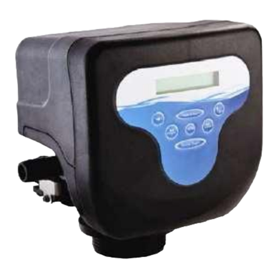
- Page 8 5. PROGRAMMING. Once the power supply adapter has been connected, the programmer must be programmed. Figure 5. Programmer Front panel. DESCRIPTION ADVANCE. Moves the pointer to set the parameters. TIME & DAY. Access to programme the time and day. INCREASE VALUES AND CONFIRMATION. Increases the value of the parameters to configure.
- Page 9 5.1. - DAY & TIME CONFIGURATION. Steps to follow: Access to the configuration menu. Move the cursor over the clock to set the hour and minute. Increase value Move Move the cursor over the weekly calendar to set the day. Confirm Move Save the programmed values.
- Page 10 5.2. - WORK MODE CONFIGURATION Valve D allows configuration of 4 different working modes: MODE 1: TIMED - Chronometrical regeneration Work Mode. The system will regenerate with the frequency of the days selected and the time established (01-99 days) Once programmed, the screen will show the following: DAY OF TIME OF...
- Page 11 5.2.1. - WORK MODE CONFIGURACION DEL: MODE 1 - TIMED. To access the Work Mode, press: Steps to follow: Access to the configuration menu. Move the cursor to the desired work (TIME). configuration: Confirm Move Save the programmed values. 5.2.1.1- TIMED CONFIGURATION & INTERVAL BETWEEN REGENERACIONS: MODE 1 - TIMED To access the Work Mode, press: Steps to follow:...
- Page 12 5.2.2. - WORK MODE CONFIGURATION: MODE 2- METER IMM. To access the Work Mode, press: Steps to follow: Access to the configuration menu. Move the cursor to the desired work configuration: (METER IMM). Confirm Move Move the cursor and confirm the desired measurement units: (L) Confirm Move...
- Page 13 5.2.3. - WORK MODE CONFIGURATION: MODE 3 - WEEK To access the Work Mode, press: Steps to follow: Access to the configuration menu. Move the cursor to the desired work configuration: (WEEK). Increase value Move Save the programmed values. 5.2.3.1. - REGENERACION TIME & DAY CONFIGURATION. MODE 3- WEEK To access the programming of the regeneration time, press: Access to the configuration menu.
- Page 14 5.2.4. - WORK MODE CONFIGURATION: MODE 4-METER DELAY To access the Work Mode, press: Steps to follow: Access to the configuration menu set the regeneration time Move the cursor to (METERDELAY). desired: Move Confirm Move the cursor and set the desired measurement Units: (L).
- Page 15 5.2.4.1. - REGENERATION TIME & TRETED WATER VOLUME CONFIGURATION: METER DELAY To access the ‘programming of the regeneration time, press: Access to the configuration menu. Move the cursor to set the regeneration time desired: Increase Move value Move the cursor to set the maximum number of days between regenerations.
- Page 16 CALCULATION TABLE TO PROGRAMME THE VOLUME OF TREATED WATER BY A D-DF-M SYSTEM DEPENDING ON THE RESIN AND HARDNESS OF THE WATER. HARDNESS ºHF FOR D-DF-M SYSTEMS 50 ºHF 40 ºHF 60 ºHF 70 ºHF 80 ºHF 90 ºHF 100 ºHF Litres of resin 30 ºHF 1000...
- Page 17 5.2.3. - CONFIGURATION OF REGENERATION CYCLE TIMES. To access the programming of the regeneration time, press: Access to the regeneration cycle times configuration menu. Move the cursor to set the minutes of each cycle. Increase Move value SEE THE TABLE ATTACHED TO SET THE VOLUME OF WATER TREATED DEPENDING ON THE SOFTENER’S RESIN BED...
- Page 18 TIMING PROGRAMME FOR D-DF-M³ SYSTEMS LITRES BACKWASH BRINE DRAW RAPID RINSE REFILL RESIN 5 min 60 min 5 min 5 min 5 min 60 min 5 min 8 min 5 min 60 min 5 min 8 min 5 min 60 min 5 min 10 min 5 min...
- Page 19 6. - SOFTENER START-UP Once the hydraulic circuit has been realised, connected to a power source and the microprocessor has been programmed, the system can be started up. Follow the steps as described below: 6.1. - How to start up the softener. Bleed the air bottle ...
- Page 20 - Once the system has been checked that it’s sucking correctly, replace the volume of water that had been sucked by setting the system to REFILL & and allow it to go to SERVICE by itself. The display will show the following information according to the mode set: MODE 1: TIME MODE 2: WEEK MODE 3: METER IMM...
- Page 21 7. - MENSAGES SHOWN ON THE SCREEN. 7.1. - AUTOMATIC LOCK. When the programmer’s keyboard hasn’t been used for a while, an automatic lock is activated, turning the light off to save electric consumption. By pressing any key, the following message will appear on the display. To unlock the controller press sequentially &...
- Page 22 8. - INFORMATION DISPLAYED ON THE SCREEN DURING SERVICE PHASE, DEPENDING ON THE CONFIGURATION SELECTED. 8.1. - CONFIGURATION: TIMED: Delayed clockwork. TIME OF DAY DAY OF THE WEEK TIME UNTIL THE STATE NEXT REGENERATION 8.2. - CONFIGURATION: WEEK: weekly clockwork. TIME OF DAY DAY OF THE WEEK TIME &...
- Page 23 9. - PARTS. ref: MA-ED-0008-EN-V16.0-MIÑO DESCALCIFICADOR D-DF-M3 & D-UF-M3.pdf...
- Page 24 ref: MA-ED-0008-EN-V16.0-MIÑO DESCALCIFICADOR D-DF-M3 & D-UF-M3.pdf...
- Page 25 10. - DIMENSIONS (Inches) ref: MA-ED-0008-EN-V16.0-MIÑO DESCALCIFICADOR D-DF-M3 & D-UF-M3.pdf...
- Page 26 11. - FAULTS, POSSIBLE CAUSES AND POSSIBLE SOLUTIONS. CAUTION: Those service procedures require that the system pressure is off, are marked with a ® symbol. When service work is finished, reconnect the water pressure to the system and perform the system start-up. Problem Probable cause Solution...
- Page 27 Uncontrollable filling flow. Remove and clean salt variable controller and sphere. Air intake in the brine line. Check all connections on the brine 8. The brine tank overflows. line for leaks. Refer to the Improper drain control for the instructions. injector.
Need help?
Do you have a question about the D-DF Series and is the answer not in the manual?
Questions and answers