
Related Manuals for MAKSIWA CBC.T

Summary of Contents for MAKSIWA CBC.T
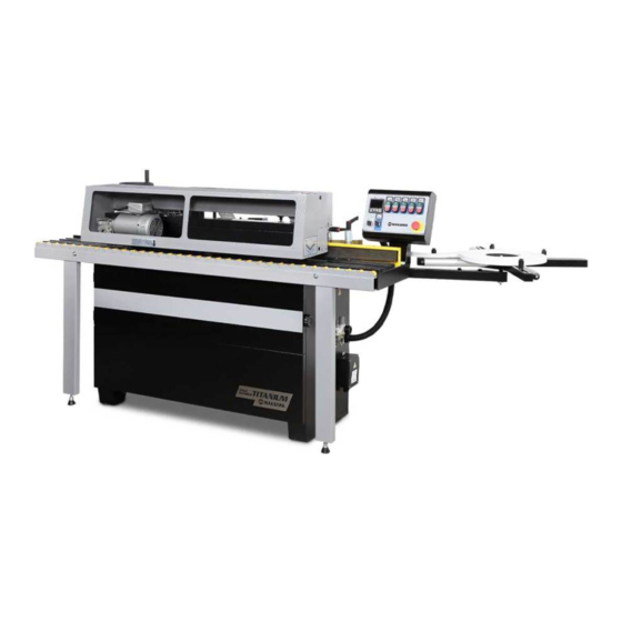
- Page 1 CBC.T Titanium Automatic Edgebander INSTRUCTION MANUAL Attention: Read this manual before using the machine.
- Page 2 Maksiwa’s highest standards of technology and quality. Your Edgebender allows you to have the highest productivity in woodworking. Besides a great finish, the CBC.T ensures that your work pieces come always precise. It should be noted that to use this machine with maximum efficiency, you should read and understand the instructions in this manual.
-
Page 3: Table Of Contents
Index 1. Safey Regulations................................04 1.1 Workspace...................................04 1.2 Electrical Safety................................04 1.3 Personal Safety.................................04 1.4 Machine Safety................................06 2. Description..................................07 2.1 Lifting and Transport...............................07 2.2 Location of Machine..............................07 2.3 Specifications................................07 2.4 Operators Position..............................08 2.5 Components................................09 2.6 Noise Levels................................10 2.7 Standard Equipment...............................10 3. Installation..................................12 3.1 Basic Assembly................................12 3.2 Assembling Detached Parts..........................13 3.3 Electrical Connections............................13... -
Page 4: Safey Regulations
Ensure that your power supply is in accordance with the rating of the machine. A 10% increase or decrease in voltage will cause power loss and overheating. All Maksiwa equipment is factory tested. If this Machine does not operate properly, first check the power supply. - Page 5 1 Safety Regulations • Always wear safety glasses, face protection, safety anti-slip shoes, and ear protection to reduce personal injury. • Always wear safety glasses, face protection, safety anti-slip shoes, and ear protection to reduce personal injury. • Do not wear loose clothing, gloves, chains, rings, bracelets or other accessories. It is also recommended to use hair protection.
-
Page 6: Machine Safety
1 Safety Regulations 1.4 Machine Safety • Turn off the machine, unplug the power cord, and wait until the working process stops, before performing any maintenance or adjustments to the machine. • Do not overload the Machine, it will perform the job better and safer if used as indicated. •... -
Page 7: Description
2 Description 2 Description This Maksiwa Automatic Edgebander Titanium CBC.T is a master piece of engineering, packet with features that will make your job easier giving you a product finish like never before. Super steady and stable, with a stainless-steel mono-block base. All operating units are easy to be accessed through the upper protection hood. -
Page 8: Operators Position
2 Description • Dust collection outlet: Ø 5” • Glue pot elements: 1,315 W • Total power installed: 7.7 KW • Feeding motor: 0.75 KW • Glue & edge: 0.18 KW • Heating elements: 5 pcs for 1.315 KW • Heating in -feed fence: 0.4 KW •... -
Page 9: Components
2 Description 2.5 Components Tape coil support 12. Pressure roller 2. Control panel 13. End trimming 3. Handle for in-feed fence 14. Top/down trimming 4. Handle wheel for pressure beam 15. Buffing unit 5. RFL system 6. Electric box Motor for end trimming unit 8. -
Page 10: Noise Levels
2 Description 2.6 Noise Levels As per ISO3744/94-ISO 7960/95 Annex norms: When working with dust tractor AVG 73.6 (dB (A)), OpE 73.1 (dB (A)) OpU 73.7 (dB(A)) Description of symbols: AVG: Medium level of acoustic pressure Level acoustic pressure operator’s entrance place. OpU level of acoustic pressure of operator’s exit place. - Page 11 2 Description • Buffering 0.12x2- 1200mm-3000RPM Voltage 380-440/50-60/3, 220-240/50-60/3. • Working table with sliding rollers and PE guide. • Front extensible support for large panels. • Tape coil roller support Ø800mm. • Rear closure with centralized dust collector Ø100mm. • Compressed air regulation unit with filter.
-
Page 12: Installation
3 Installation 3 Installation To protect the machine from damage during transportation, we assembled the control panel upside down. Please change the direction positioning it correctly. The handle was also removed and packed separately with the glue pot cover. Fix the handle and glue pot cover on the correct position before using the machine. -
Page 13: Assembling Detached Parts
3 Installation 3.2 Assembling Detached Parts For transport the tape coil support can be detached from the machine. 2. Fix the plate A to the machine table with the 2 screws D. 3. Place the tape coil support B on plate A placing the nuts in their correct position then tighten the screw C. -
Page 14: Pneumatic Connection
3 Installation 3.4 Pneumatic Connection The filter/pressure regulator with outflow of condensation, and the quick fitting are situated on the side of the machine. • Always connect the machine to the compressed air unit. • Ensure compressed air is at least 6 kg/cm². •... -
Page 15: Control Panel
4 Control Panel 4 Control Panel • Buttons A can turn on every unit. Green button is turn on; Red button is turn off. • Button B is the emergency stop. When pressing emergency stop, actives will stop immediately and all the machine functions are in locked position. -
Page 16: Operation
5 Operation 5 Operation 5.1 Adjust in-feed Fence To apply the edge on the panel correctly, it is necessary to keep the panel parallel to the “Edging line”. By “Edging line” we mean the alignment of: In-feed fence B. 2. Pressure rollers. 3. -
Page 17: Edge Feeding
5 Operation 5.3 Edge Feeding Edge Positioning Put the edge between the two stainless steel guides B. 2. Keep the vertical position of the edge with the hold down knobs A which is coupled with a screw. 3. Set the knob and the screw 45° slot to achieve the vertical setting of the coil. -
Page 18: Glue Pot Unit
5 Operation 5.4 Glue pot unit The glue pot unit spreads the hot melting glue on the work-piece to be edged. Thermo adjustment on the PLC checks the heating and functioning of the glue pot. For correct use please follow instructions: Fill the glue pot to approximately 1cm below edge of the pot. -
Page 19: Pressure Rollers Unit
5 Operation How to change glue Turn on machine, and the glue pot should be cold. If the glue pot is hot, please wait till it cools down. 2. When the thermoregulatory shows approx. 80-90°C, turn off the main switch. 3. -
Page 20: Front/Rear Trimming
5 Operation 5.6 Front/Rear Trimming This unit is extremely precise, automatically end-trims both froth/rear exceeding edge. Made of solid steel, it guarantees a clean, accurate cut on the leading and tailing edges of the panel being processed. This is done completely automatic and the cut is referenced directly from the panel via micro-switches with no need to adjustments when running different length panels. -
Page 21: Top/Down Trimming Unit
5 Operation Change the Belt Take off the belt protection closure by loose the screws A. 2. Take off the old belt and replace with the new one. Check the Belt Tensioning Loose the 4 fixing screws of the motor. The 4 fixing screws can be reached with an Allan screw by turning the toothed pulley until the 2 holes B coincide with the 4 motor screws. -
Page 22: Buffing Unit
5 Operation Change Cutters Take off the cover. 2. Use spanner to loosen the grains which lock the gib of the knife. Take out the gib and the knife. 3. Change the knife and put it back on the gib. 4. -
Page 23: Panel Belt Feeder
5 Operation Change Buffers Loosen locking screw A. 2. Pull out the flange B. 3. Pull out the buffers and remount a new set of buffers (2) following mounting scheme in. 4. Assemble them all back. Important! When mount or adjust buffers, adjust the buffer 2/3 forward to touch the work peace, only 1/3 under the fence. -
Page 24: Maintenance
6 Maintenance 6 Maintenance 6.1 Cleaning Before changing any blades, please press emergency stop and wait till the blades are all stop! Even already turned off the motor, the blades may have inertia and keep running. Clean the pressure rollers and the small roller on the bed from glue residues. Note: Before touching parts with solvent make sure they have been cool down. -
Page 25: Exploded View
7 Exploded View... - Page 26 7 Exploded View ITEM PART NO. PARTS NAME SIZE Q`TY NOTE 721010 Pressure Beam Bracket 994301 Thrust Bearing 51201 721004 Precision Screw Pole M14*P1.5 721013 Bearing Bushing 721427 Hex Nut M12x1.75p 721002 Adapter Shaft BD452001 Bushing Bearing DU4520 BD452002 Bushing Bearing DU4520F 721006A Slider Bracket...
- Page 27 7 Exploded View...
- Page 28 7 Exploded View ITEM PART NO. PARTS NAME SIZE Q`TY NOTE 721028 Conveyer Seat 721020 Conveyer By The Board 721018 Roll Wheel 994353 Bushing Bearing DU2020 721023 Roll Wheel 721022 Transmission Shaft KD060620 Flat Key 6*6*20 KD060640 Flat Key 6*6*40 721019 Shaft SR081600...
- Page 29 7 Exploded View ITEM PART NO. PARTS NAME SIZE Q`TY NOTE NL061000 Hex Nut 721526 plank 135051-A hairbrush WF061620 Washer SR060500 Cap Screw M6X25L AB721024 Transmission pressure wheel group...
- Page 30 7 Exploded View ITEM PART NO. PARTS NAME SIZE NOTE 721032 Adjustment Column WF040810 Washer 4*8*1T WS080000 Spring Washer SR080400 Cap Screw M8*20L 721036C Locate Plug 721035 Plug Fixed Plate NH061000 Hex Nut SP049200 Pan Head Screw M4*8L SJ080404 Round Socket Head Cap Screw M8*20L WF081820 Washer...
- Page 31 7 Exploded View...
- Page 32 7 Exploded View ITEM PART NO. PARTS NAME SIZE Q`TY NOTE BL210402 Linear Bearing LM12 BB600204 Ball Bearing 6002 LLB 721182 Six Hexagonal Column 721043 Spindle Cover 721061 Fixer Plate WW101503 Wave-Type Gasket 10*15 721060 Adapter Shaft 721056 Plum Nut 721055 Adjustment Screw Pole M8*P1.25...
- Page 33 7 Exploded View ITEM PART NO. PARTS NAME SIZE Q`TY NOTE WF062330 Washer 6*23*3T 721059 Spring NL061000 Nylon Nut 721044 Upside Spindle SR059400 Cap Screw M5*16L 721049 Upside Tool AB721049A Low side Tool Set. 44A-1 721049A-1 44A-2 721049A-2 44A-3 721049A-3 721071 Lock Nut M10*P0.75...
- Page 34 7 Exploded View...
- Page 35 7 Exploded View ITEM PART NO. PART NAME SIZE Q`TY NOTE 721048 Low side Sliding Bracket BL210402 Linear Bearing LM12 721052 Low side Shaft BB600204 Ball Bearing 6002 LLB 721051 Low side Spindle 721182 Six Hexagonal Column 721043 Spindle Cover 721061 Fixer Plate WW101503...
- Page 36 7 Exploded View ITEM PART NO. PART NAME SIZE Q`TY NOTE 35A-2 721053A-2 35A-3 721053A-3 721071 Lock Nut M10*P0.75 721064 Position Indicator DA0406-12/5-1-E-0 WS050000 Spring Washer SR0694003 Cap Screw M6*16L WF061620 Washer M6*16*2.0 SS069150 Set Screw M6*6L SR060400 Cap Screw M6*20L WS060000 Spring Washer...
- Page 37 7 Exploded View...
- Page 38 7 Exploded View ITEM PART NO. PART NAME SIZE Q`TY NOTE 721076 Rail Seat 721077 Chrome Rod Park 721079 Platen 721080 Platen 721087 Fuselage Connecting Plate 721086 Motor Movements Block 721084 Motor Fixed Plate 721089 Positioning Ring 721088 Compression Spring SR0602003 Cap Screw M6*10L...
- Page 39 7 Exploded View...
- Page 40 7 Exploded View ITEM PART NO PARTS NAME SIZE Q`TY NOTE 721093 Cutter Plate 721103 Tool Fixed Block 721094 Guides 721102 Locate Plate 721092 Locate Block 721101 Cutter 721091 Locate Plate SM069400 Countersunk Head Cap Screw M6*16L SM060400 Countersunk Head Cap Screw M6*20L SM069300 Countersunk Head Cap Screw...
- Page 41 7 Exploded View...
- Page 42 7 Exploded View ITEM PART NO. PART NAME SIZE Q`TY NOTE 721106 Support Rib 721109 Edge with a Bracket 721107 Four Corners of the Nut 721108 Wheel WF104030 Washer Ø10*Ø40*3t NH101700 721105 Screw Pole M10*150L SJ089400 Round Socket Head Cap Screw M8*16L WF081820 Washer...
- Page 43 7 Exploded View ITEM PART NO PARTS NAME SIZE Q`TY NOTE 721113 Left Guides 721112 Right Guides 721114 Stage Screw 721115 Plum Nut WF051210 Washer Ø5*Ø12*1t SH089300 Hex Head Screw M8*12L NF081300 Flange Hex Nut WF061310 Washer Ø6*Ø13*1t SR060200 Cap Screw M6*10L...
- Page 44 7 Exploded View ITEM PART NO. PART NAME SIZE Q`TY NOTE 721117 Every Ring 721118 Fixed Plate 721119 Wheel 721120 Wheel Spindle 721122 Wheel Spindle 721124 Support Block 721128 Fixed Block SM069300 Countersunk Head Cap Screw M6*12L WF081820 Washer Ø8*Ø18*2t SR069400 Cap Screw M6*16L...
- Page 45 7 Exploded View ITEM PART NO. PART NAME SIZE Q`TY NOTE 721123 Wheel BB600403A Ball Bearing 6004LLU 721125 Y-type Connector NH061000 Hex Nut NL061000 Nylon Nut SJ059200 Round Socket Head Cap Screw M5*8L BD152001 Dry Bearing DU1520 721116 Fixed Base SS089200 Set Screw M8*8L...
- Page 46 7 Exploded View...
- Page 47 7 Exploded View ITEM PART NO. PARTS NAME SIZE Q`TY NOTE 721417 Extension Bracket 721132 721137 Gasket 721536 Wheel Platform 721131A Body 721138-3 By the Board AB205397A-N Limits Switch (Asm.) 709409 Outlet Beads 136013 Outlet Beads PG13.5 AB721136 Limits Switch (Asm.) AB721339-N Distribution Bottom Plate 3~ 380V...
- Page 48 7 Exploded View ITEM PART NO. PARTS NAME SIZE Q`TY NOTE AB994809A Power switch group 3~380~415V 50Hz,CE AB994809-2 Power switch group 1~220~240V 60Hz,CSA AB994809-1 Power switch group 3~220~240V 60Hz,CSA 1 721145 Switch Box 721143 Extension of the supper Block 994353 Bushing Bearing 721144A Extension rod...
- Page 49 7 Exploded View ITEM PART NO. PARTS NAME SIZE Q`TY NOTE 998808 Wave Tube N-MGQ32-34B 204197 Wave Tube NGN-28B...
- Page 50 7 Exploded View ITEM PART NO. PARTS NAME SIZE Q`TY NOTE 721151 Base Bracket 721152 Limit Block 721147 Slider 721146 Fixed Block 721153 Board Plate 721149 Screw Pole 721148 Adjustment Screw Pole 721155 Heater Plate Cover 722377 Heater 220V 400W V1.1 SH089300 Hex Head Bolt...
- Page 51 7 Exploded View...
- Page 52 7 Exploded View ITEM PART NO PARTS NAME SIZE Q`TY NOTE 721161 Fixed Plate 721162 Booster Plate 721163 Wheel 721164 Bearing Fixed Plate 721165 Clutch Plate 721173 Wheel Shaft 721169 721166 Shaft 721175 Wheel 721176 Gear 721177 Fixed Bracket 721179 Transmission Shaft 721180 Bearing Fixed Plate...
- Page 53 7 Exploded View ITEM PART NO PARTS NAME SIZE Q`TY NOTE SH069400 Hex Head Bolt M6*16L SR069300 Cap Screw M6*12L WS040000 Spring Washer WF040810 Washer Ø4*Ø8*1t 200964 Shaft 992607 Washer Ø10*Ø20*0.2T WS050000 Spring Washer...
- Page 54 7 Exploded View...
- Page 55 7 Exploded View ITEM PART NO PARTS NAME SIZE Q`TY NOTE 721186 Translation Base 721191 Chrome Rod Park Ø18*128L BB600203A Ball Bearing 6002 LLU 721206 Chrome Rod Park Ø10*155L 721188 Fixed Plate 721187 Chrome Rod Park Ø16*350L 721194 Lifting Block BD102001 Dry Bearing DU1020...
- Page 56 7 Exploded View ITEM PART NO PARTS NAME SIZE Q`TY NOTE 721204 Buffer Blocks WF082030 Washer M8*Ø20*3.0T WF061920 Washer M6*Ø19*2.0T WS060000 Spring Washer SR069400 Cap Screw M6*16L WF051210 Washer M5*Ø12*1T SH050200 Hex Head Bolt M5*10L 721185 Buffer Blocks 721207 Spring WS100000 Spring Washer SJ080500...
- Page 57 7 Exploded View...
- Page 58 7 Exploded View ITEM PART NO. PART NAME SIZE Q`TY NOTE MA721216 MOTOR 1/4HP(0.18KW) 2P 220/380V 3~ MA721216A MOTOR 1/4HP(0.18KW) 2P 220V 1~ 721215 Motor Fixed Bracket 721221 Support By the Board 721227A plank BB692002 Ball Bearing 692ZZ SM059400 shallow Cap Screw M5x16 SS0399003 Set Screw...
- Page 59 7 Exploded View ITEM PART NO. PART NAME SIZE Q`TY NOTE WF061920 Washer SR059400 Cap Screw M5*16L 721227B plank V1.1 WS050000 Spring Washer SR059400 Cap Screw M5*16L IM721001 Motor Cord 0.5mm x 4C 380V 3~ CE(V1.1) IM721031 Motor Cord 0.75mm x 3C 220V 1~ CE(V1.1) 992622...
- Page 60 7 Exploded View...
- Page 61 7 Exploded View ITEM PART NO PARTS NAME SIZE Q`TY NOTE 721236 Low side Pressure Plate 721237 Upside Pressure Plate 721238 Chrome Rod Park Ø10*90L 721239 Adjustment Screw M10*P1.5 721240 Plum Nut 721242 Protection Plate 721244 Spring Flakes SH050200 Hex head Bolt M5*10L WS050000 Spring Washer...
- Page 62 7 Exploded View...
- Page 63 7 Exploded View ITEM PART NO PARTS NAME SIZE Q`TY NOTE 721253 SPREAD GLUE BASE 721255 SPREAD GLUE SHAFT 721247 DISC WASHER WF253510 Flat Washer Ø25*Ø35*1T 721252 LOCKING NUT(& STAR WASHER) BB600502A BALL BEARUNG 6005ZZ 721246 BUSHING 721248 BUSHING RR470000 RETAINING RING BB600500A BALL BEARUNG...
- Page 64 7 Exploded View...
- Page 65 7 Exploded View ITEM PART NO. PARTS NAME SIZE Q`TY NOTE 721261 LOCATE BLOCK 721262 SPACER 721264 LOCATE BLOCK 721266 COVER PLATE 721267 ADJUST BSAE 721268 COVER PLATE 721269 COVER PLATE 721270 GUIDE PLATE 721272 SHAFT 721273 ADJUST BLOCK 721274 LOCATE PLATE 721275 HEATER...
- Page 66 7 Exploded View ITEM PART NO. PARTS NAME SIZE Q`TY NOTE SR0594403 HEX SOCKET BOLT M5x16L WS050000 SPRING WASHER WF051210 FLAT WASHER Ø5xØ12x1t NF061000 FLANGE NUT SR0604403 HEX SOCKET BOLT M6x20L SR060400 Cap Screw M6*1*20 WS060000 SPRING WASHER WF061320 FLAT WASHER M6*Ø13 721549 GLUE BARREL UPPER COVER...
- Page 67 7 Exploded View...
- Page 68 7 Exploded View ITEM PART NO. PARTS NAME SIZE Q`TY NOTE 721281 Cones 721286 Electricity Boards 721283 Fixed Plate 721293 Non-Asbestos Gasket 721284 Heater 220V 160W 721285 Heater 220V 250W 721282 Brass 300mm 709411 Outlet Beads PG 11 721287 Connector Box 721291 Lubrication Of Joints 721289...
- Page 69 7 Exploded View...
- Page 70 7 Exploded View ITEM PART NO. PARTS NAME SIZE Q`TY NOTE 721312 Motor Fixed Plate V1.1 721297 Spindle Bracket 721299A Fixed Bracket 721304 Spring 721305 Gasket BB600502A Ball Bearing 6005ZZ 721313 Ring RS250000 C-Type Ring 721308 Spindle Connector Gear 721306 Plum Nut 721303 Screw Plot...
- Page 71 7 Exploded View ITEM PART NO. PARTS NAME SIZE Q`TY NOTE SH080600 Hex Head Bolt M8*30L SH059300 Hex Head Bolt M5*12L SH060401 Hex Head Bolt M6*20L WF061620 Washer Ø6*Ø16*2t SH0894403 Hex Head Bolt M8*16L IM721004 Motor Cord 0.5mm x 4C 380V 3~ CE IM721034 Motor Cord...
- Page 72 7 Exploded View...
- Page 73 7 Exploded View ITEM PART NO. PARTS NAME SIZE Q`TY NOTE MA721321A Motor 1/4HP(0.18KW) 2P S/220V 1~ MA721321B Motor 1/4HP(0.18KW) 2P S/220V 1~ MA721321 Motor 1/6HP(0.12KW) 2P S/220/380V 721319 Motor Fixed Plate 721317 Wheel 5" SR059400 Cap Screw M5*16L WS050000 Spring Washer 721324 Fixed Plate...
- Page 74 7 Exploded View...
- Page 75 7 Exploded View ITEM PART NO PARTS NAME SIZE Q`TY NOTE 721402 Back Cover 721546 Front Cover 612030 Living leaf BR000043 Pop Rivet 4-3 Ø3.2 x 8.9 721333 Transparent Cover 201624 Handle 136826 Hinge LY-4050 721550 plank SR059300 Cap Screw M5*12L 135041 Knob...
- Page 76 7 Exploded View ITEM PART NO PARTS NAME SIZE Q`TY NOTE 205397A Limits Switch IC721007 SWITCH CORD 0.5mm²x2C...
- Page 77 7 Exploded View ITEM PART NO PARTS NAME SIZE Q`TY NOTE 721037 Door Safety Switch AZD-1001T 709411 Outlet Beads PG11 IC721041 SWITCH CORD 0.5mm²x2C ITEM PART NO PARTS NAME SIZE Q`TY NOTE 721100 Cylinders Ø63*20ST 721097 Rapid Exhaust Valve QE01-BK 721373 Valve Silencer PT1/4"...
- Page 78 7 Exploded View ITEM PART PARTS NAME SIZE Q`TY NOTE 721350 Aluminum Base 721351 Solenoid Valve 4V210-08H SP030800 Pan Head Screw M3*40L WS030000 Spring Washer 721357 L-Type EPL10-2 721358 Threaded Through EPC6-2 721359 Plug PT1/4" 721365 Threaded Through EPC8-2 721373 Valve Silencer PT1/4"...
-
Page 79: Terms Of Warranty
8 Terms of Warranty 8 Terms of Warranty MAKSIWA assures the owner that their equipment, identified by the Serial number issued on the Warranty Terms. The equipment under warranty, for two (2) years, is as followed: The warranty period begins on the date of the Warranty Terms below. - Page 80 For your safety, trust the repairs, maintenance and adjustments (including inspection and replacement) for technical assistance recommended by MAKSIWA, always use genuine spare parts and accessories, reassembling to its original machine the same way. MODEL: SERIAL NUMBER: DATE: LOT NUMBER: Imported by: Maksiwa International Inc.
Need help?
Do you have a question about the CBC.T and is the answer not in the manual?
Questions and answers