
Related Manuals for AXITEC AXIstorage Li SH Series


Summary of Contents for AXITEC AXIstorage Li SH Series
- Page 1 Installation Instruction AXIstorage Li SH for SMA Sunny Boy Storage 3.7 / 5.0 / 6.0 AXITEC Energy GmbH & Co. KG, Otto-Lilienthal-Str. 5, 71034 Böblingen, Germany, +49 7031-6288-5173, www.axitecsolar.com...
-
Page 2: Table Of Contents
Inhalt Safety ..............................4 Important notes on this manual ....................4 1.1.1 Purpose ..........................4 1.1.2 Target group ..........................4 1.1.3 Storage ..........................4 Symbol explanations ........................5 1.2.1 Explanations regarding safety instructions and warnings .............5 1.2.2 Explanation of pictograms and symbols ................6 Battery application area ........................7 1.3.1 Appropriate use ........................7 1.3.2... - Page 3 Assembly ............................ 15 3.3.1 Installing AXIstorage Li SH – Installation of Energypacks ........... 15 3.3.2 Connect Energypacks next to each other in series ............18 3.3.3 Closing the housing of the battery system ................. 19 3.3.4 Subsequent installation of additional battery modules ............. 20 3.3.5 Disposal measures ......................
-
Page 4: Safety
1 Safety Before installing the battery system, read these instructions carefully. Please follow the safety and warning instructions carefully to avoid damage to persons, objects and the environment. CAUTION Risk of burns if you fail to adhere to the safety instructions. During operation, heat can be generated by live parts, overload, arc or short circuit. -
Page 5: Symbol Explanations
Symbol explanations 1.2.1 Explanations regarding safety instructions and warnings Safety Instructions are universally valid and can be found in a safety chapter or at the beginning of a chapter. Warnings are placed directly before behavioral guidelines. They help you to avoid dangers during an upcoming operation. -
Page 6: Explanation Of Pictograms And Symbols
1.2.2 Explanation of pictograms and symbols Symbols Declaration General warning sign. Note additional information. Warning of electrical voltage. Warning of dangers from batteries that are being charged. Warning of flammable substances. Hot surface warning. Warning of hand injuries. No access for persons who have pacemakers or implanted defibrillators. Manual lifting prohibited. -
Page 7: Battery Application Area
In a battery system, 3 to 6 Energypacks can be connected to one another in series. Axitec Energy GmbH & Co.KG is not liable for personal injury and/or material damage due to improper use of the energy storage system. -
Page 8: Main Hazards
Fire Qualification of the users Only the electricians qualified by the Axitec Energy or the Axitec Energy itself may work with the battery system. Do not leave the children unattended or allow them to be near the battery system. -
Page 9: Personal Protective Equipment (Ppe)
Personal protective equipment (PPE) Use foot protection and hand protection during assembly. Emergency instructions 1.7.1 Measures in case of fire Do not inhale smoke and vapors. Report a lithium-ion fire to the fire department. If possible: Close the doors. If possible: Cool the Energypack with water. Avoid contact with the extinguishing water! 1.7.2 Measures after gases or liquids have escaped Escaping gases... -
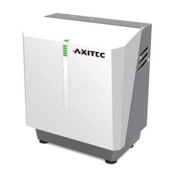
Page 10: Product Description
2 Product description Important information about the product Overall view Figure 1 Overall view of battery system. 2.1.1 Conformity The following standards, laws and guidelines were taken into account during the development of the Energypack: EU directive with CE labelling obligation ... -
Page 11: Scope Of Delivery
2.2 Scope of delivery AXIstorage Li SH system housing Installation kit (in system housing) is included: 7 RJ45 patch cables 12 screws M5x10 3 Dummy sockets, power plugs 2 PG connections ▪ 1 Three-hole cable bushing ▪... -
Page 12: Technical Data
2.3 Technical data 2.3.1 Performance features Modules in series Energy content 9,7 kWh / 12,9 kWh / 16,1 kWh / 19,3 kWh / (nom./usable) 7,5 kWh 10 kWh 12,5 kWh 15 kWh Nominal voltage 155 V 207 V 258 V 310 V End-of-charge voltage 170 V... -
Page 13: Ambient Conditions
All cables have a length of about 40 cm. NOTE: Extension of the power cables must not exceed the following lengths: 6 mm cable cross section: 10 mm cable cross section: 8 m The Energypack has one socket which contains (+) and (-) as power contacts and two RJ45 sockets which contain CAN bus and status and signal lines: ... -
Page 14: Commissioning
3 Commissioning 3.1 Safety Instructions The installation may only be carried out by qualified electricians according to IEC 60204-1 (International Electrotechnical Commission). The housing including electronics weighs 41 kg. One Energypack weighs 22 kg. Heavy lifting can cause a disturbance of the musculoskeletal system. ... -
Page 15: Mounting
3.2.3 Mounting The installation location for the battery system and the inverter have been determined. Recommended mounting: Install the wall bracket of the inverter. Hook the inverter into its bracket. Unscrew the cover of the connection area. If not already done, remove the cover from the battery system housing: ... - Page 16 CAUTION Ergonomic hazards due to heavy lifting. Lifting the Energypack can cause a disturbance of the musculoskeletal system. Should it be necessary, be sure not to lift the module alone. Use a lifting aid, when necessary ATTENTION Incorrect installation due to damaged or contaminated Energypack. Only faultless modules may be mounted.
- Page 17 with with 3 Energypacks 4 Energypacks with with 5 Energypacks 6 Energypacks Figure 2: Insert 3 to 6 Energypacks NOTE: For best cooling, we recommend that you install the battery modules as shown in Figure 2. Screw the downholder to the right and left of the base of the system housing. Screw each Energypack with two screws (M5) to the downholder/grounding support.
-
Page 18: Connect Energypacks Next To Each Other In Series
Use the patch cables to connect the BMS master (left of the two RJ45 sockets) with the installed Energypack. For example, refer to Figure 4 Figure 4: Connect the Energypack to the BMS master using the patch cables connect the last battery module to the left RJ45 socket (RJ45-B) in the BMS master. 3.3.2 Connect Energypacks next to each other in series WARNING Electric shock from live parts. -
Page 19: Closing The Housing Of The Battery System
Remove the safety cover of the "Power" sockets. Figure 5: Power path with switching devices and BMS Insert the power plug for the respective Energypack until it clicks into place. For example, refer to Figure 5. Check by pulling the power plugs to make sure that the latching is engaged. If there are less than 6 Energypacks: Fit the power plugs not required with the dummy sockets supplied. -
Page 20: Subsequent Installation Of Additional Battery Modules
3.3.4 Subsequent installation of additional battery modules check the voltage of the modules. This should be between 46 V and 56 V. adjust the voltage of the battery system to ±1 V for the new modules (see also Appendix 8.3: Adjusting the system voltage with SMA SB Storage). An exactly adjusted module voltage avoids system voltage adjustment and allows immediate access to the entire capacity. -
Page 21: Connecting The Inverter
3.4 Connecting the inverter 3.4.1 SMA Sunny Boy Storage 3.7 / 5.0 / 6.0 Feed the DC power cable, PE as well as the communication cable(s) through the respective PG screw glands into the connection compartment of the inverter. Figure 6: Connecting the SMA SB Storage to the AXIstorage Li SH Connect the cables in the inverter according to the Sunny Boy Storage 3.7 / 5.0 / 6.0 operating instructions. -
Page 22: Putting The Axistorage Li Sh System Into Operation
3.5 Putting the AXIstorage Li SH system into operation Put the inverter into operation Set up inverter communication so that battery system can be set up Switch the DC disconnector on the left side of the AXIstorage Li SH to "on". Commission the storage system according to the operating manual of the connected inverter. -
Page 23: Storage Conditions
5.2 Storage conditions 5.2.1 Storage period Do not store the module for more than six months from the date of manufacture (see type label). The module must be recharged for longer storage periods. 5.2.2 Physikcal conditions Store the module in a dry place, protected from solar radiation, maximum 2000 m above sea level. The following conditions should prevail on an average: ... -
Page 24: Disposal
7 Disposal Batteries may not be disposed of in household garbage. As a consumer, you are legally obligated to return used batteries. The return is free of charge. If lithium batteries are not disposed of properly, fire or leakage of hazardous substances may cause damage to health and the environment. -
Page 25: Further Directories
8 Further directories 8.1 BMS Master, DC-DC converter and relay in AXIstorage Li SH 8.2 Assignment BMS master inverter interface AXIstorage Li SH SMA Sunny Boy Storage 3.7 / 5.0 / 6.0 assignment strand colour [BATx] CAN H yellow CAN L white RS485A n.c. -
Page 26: Setting The System Voltage With Sma Sb Storage
8.3 Setting the system voltage with SMA SB Storage To add Energypacks, the system voltage must be adjusted to the module voltage. For this purpose, set the Sunny Boy Storage to a specific SOC: Open the user interface of the Sunny Boy Storage. Register as installer. -
Page 27: List Of Abbreviations
8.5 List of abbreviations Term Definition Batterie Management System Personal protective equipment Combined heat and power Open circuit voltage State of charge 8.6 List of tables Table 1: Warnings............................5 Table 2: Explanation of the symbols used.....................6 Table 3: Structure of warnings ........................12 Table 4: Overview LED status codes...................... -
Page 28: Addresses, Identification And Notes
9 Addresses, identification and notes Imprint Axitec Energy GmbH & Co. KG Otto-Lilienthal-Straße 5 71034 Böblingen Germany Tel.: +49 (0) 7031 6288-5186 energy@axitecsolar.com Product- AXIstorage Li SH (system housing), Item no. AY10469 identification Energypack (modular battery), Item no. AY10468 compatible with SMA Sunny Boy Storage 3.7 / 5.0 / 6.0...
Need help?
Do you have a question about the AXIstorage Li SH Series and is the answer not in the manual?
Questions and answers