Table of Contents
Advertisement
Quick Links
2XX-EIP
EtherNet/IP Interface Card
For 200 Series Indicators
(205, 210, 215 and 225)
INSTALLATION MANUAL
8200-M554-O1 Rev A
203 E. Daugherty, Webb City, MO 64870 USA
Printed in USA
Ph: 417-673-4631 y Fax: 417-673-2153
03/09
www.cardinalscale.com
Technical Support: Ph: 866-254-8261 x tech@cardet.com
8200-M554-O1 x 2XX-EIP
Page 1
Advertisement
Table of Contents

Related Manuals for Cardinal 2XX-EIP


Summary of Contents for Cardinal 2XX-EIP
- Page 1 For 200 Series Indicators (205, 210, 215 and 225) INSTALLATION MANUAL 8200-M554-O1 Rev A 203 E. Daugherty, Webb City, MO 64870 USA Printed in USA Ph: 417-673-4631 y Fax: 417-673-2153 03/09 www.cardinalscale.com Technical Support: Ph: 866-254-8261 x tech@cardet.com 8200-M554-O1 x 2XX-EIP Page 1...
- Page 2 8200-M554-O1 x 2XX-EIP Page 2...
-
Page 3: Specifications
A single RJ-45 connector is provided to connect to the EtherNet IP network. The 2XX-EIP supports 10/100 Mbit, full or half duplex operation. The purpose of this manual is to provide you with a guide through setup and installation of the 2XX-EIP EtherNet/IP interface card. -
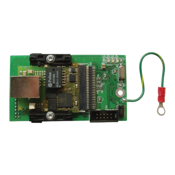
Page 4: Installation
Refer to Figure No. 2. 9. Connect the ground wire from the option card by placing the ring terminal over the 6-32 threaded stud. Attach 10. Reinstall the washer and 6-32 nut and tighten. Ground Here Figure No 2 8200-M554-O1 x 2XX-EIP Page 2... - Page 5 2. Insert the Ethernet cable (CAT 5 or equivalent) through the gland connector and into the enclosure. 3. Consult your network administrator for the proper procedure to terminate the cable. 4. After the cable has been terminated, plug the cable into the RJ-45 jack on the 2XX-EIP. Item # Description...
-
Page 6: Re-Installing The Rear Panel
TCP/IP ADDRESS SETUP On an EtherNet/IP network, each node must be assigned its own unique TCP/IP address. The 2XX-EIP EtherNet IP interface card IP address is set using the Anybus IPconfig Tool utility provided on the 2XX-EIP Config File CD (8200-M533-O1). - Page 7 PLC. Start by right click the EtherNet/IP module/bridge in the I/O configuration, and select “New Module”. Now a dialogue window will appear. In this dialogue window, select “Generic Ethernet module” and press OK. 8200-M554-O1 x 2XX-EIP Page 5...
- Page 8 With the name entered, press Next. In the next dialogue box enter a value for the time between each scan of the module, called Request Packet Interval (RPI). Make sure that “Inhibit Module” isn’t checked. After this, press Finish. 8200-M554-O1 x 2XX-EIP Page 6...
- Page 9 The configuration instance will be created even if we selected zero as its size. The Cardinal_2XX:I tag is data coming from the module and Cardinal_2XX:O tag holds data going to the module. 8200-M554-O1 x 2XX-EIP Page 7...
- Page 10 Float Byte 1 Float Byte 2 Float Byte 3 Input The weight data begins at Data[0] and uses the next four bytes to produce a floating point program tag. Float = (Data[0], Data[1], Data[2], Data[3]) 8200-M554-O1 x 2XX-EIP Page 8...
- Page 11 Technical and Installation manual of your indicator for instructions on enabling and using the PWC feature. Bit0 PWC1 0=off/1=on Bit1 PWC2 0=off/1=on Bit2 PWC3 0=off/1=on Bit3 PWC4 0=off/1=on Bit4 PWC5 0=off/1=on Bit5 PWC6 0=off/1=on Bit6 PWC7 0=off/1=on Bit7 PWC8 0=off/1=on 8200-M554-O1 x 2XX-EIP Page 9...
- Page 12 Bit13 PWC6 requires float point value be sent in Bytes 4, 5, 6 & 7 Bit14 PWC7 requires float point value be sent in Bytes 4, 5, 6 & 7 Bit15 PWC8 requires float point value be sent in Bytes 4, 5, 6 & 7 8200-M554-O1 x 2XX-EIP Page 10...
-
Page 13: Troubleshooting
Controlled by a Scanner in Run state Green, Flashing Not configured, or Scanner in Idle state Major fault (EXCEPTION-state, FATAL error etc.) Red, Flashing Recoverable fault(s) Link/Activity No link, no activity Green Link established Green, flickering Activity 8200-M554-O1 x 2XX-EIP Page 11... - Page 15 2XX-EIP ADDENDUM For 225 Indicator 8200-M554-O1 x 2XX-EIP Page 12...
-
Page 16: Key Lockout
SETUP MENU #3 1. G/N ACCUMS=XXX 6. KEY LOCKOUT 2. BACK LITE=XX 3. PASSWORD 4. 2xx-EIP Enter Selection: 0 ^PREV vEXIT There are no setup variables for the EIP option card, going to this menu just assures the operator that the 225 can detect the presence of the option card. - Page 17 COMMUNICATIONS Date Sent From the XX To The PLC: Word0 Float point weight. Byte 0 Float point weight. Byte 1 Float point weight. Byte 2 Float point weight. Byte 3 Word1 Scale Number (Bits 4-7) Weight Status. See bit definitions below Word2 Cmd1.
- Page 18 SCALE NUMBER The scale number is encoded as a four bit binary number, 1 through the number of scales available. Eg. Scale #1 (00010000), Scale #2 (00100000), Scale #3 (00110000), and Total scale (01000000). Bit0 (not used) Bit1 (not used) Bit2 (not used) Bit3...
Need help?
Do you have a question about the 2XX-EIP and is the answer not in the manual?
Questions and answers