
Related Manuals for Cardinal 2-EIP Series


Summary of Contents for Cardinal 2-EIP Series
- Page 1 2XX-EIP EtherNet/IP Interface Card Installation and Setup Manual For 205, 210, and 225 Weight Indicators 8200-M554-O1 Rev C 2XX-EIP Installation and Setup Manual...
- Page 2 8200-M554-O1 Rev C 2XX-EIP Installation and Setup Manual...
-
Page 3: Specifications
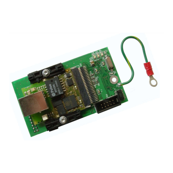
INTRODUCTION The 2XX-EIP has been designed for the industrial environment where interfacing through an EtherNet IP network is desired. When coupled with a 205, 210, or 225 digital weight indicator, it can provide the weight reading and control of multiple scale commands. The interface card resides in the main enclosure of the indicator and has a 16-pin dual in-line connector to provide an easy connection to the indicator's internal hardware. -
Page 4: Installation
INSTALLATION Mounting the 2XX-EIP Option Card NOTE: Should your indicator come with the 2XX-EIP option card already installed, the following section describing mounting does not apply. Proceed to the Node Address Setup section. CAUTION! This board contains static sensitive components. Improper handling can result in damage to or destruction of the components or board. - Page 5 INSTALLATION, CONT. Mounting the 2XX-EIP Option Card, Cont. 205/210 Main PCB NOTE: 205 Main PCB shown. The 210 Main PCB will have connector P2, REMOTE OUTPUTS, and J7, REMOTE OUTPUT SRC jumper installed. ATTACH GROUND WIRE THREADED TO THREADED STAND-OFF STUD HERE OPTION BOARD...
- Page 6 INSTALLATION, CONT. Ethernet Cable Installation 1. Loosen an unused cable gland connector for the cable. 2. Insert the Ethernet cable (CAT 5 or equivalent) through the gland connector and into the enclosure. 3. Consult your network administrator for the proper procedure to terminate the cable. 4.
-
Page 7: Re-Installing The Rear Panel
RE-INSTALLING THE REAR PANEL When the installation is complete: 1. Remove the excess cable from the indicator enclosure. 2. Make certain no cables or wires are exposed between the main housing and rear panel and then place the rear panel onto the main housing. 3. - Page 8 225 INDICATOR SETUP, CONT. SETUP MENU #3 1. G/N ACCUMS=XXX 6. KEY LOCKOUT 2. BACK LITE= X 7. LRPort=COM3 3. PASSWORD 4. 2XX-EIP/MODBUSTCP 5. BADGE RDR 10. Send Grs En=XXX Enter Selection: 0 PREV EXIT With SETUP MENU #3 displayed, press the 4 key and then the ENTER key. The display will change to show the 2XX-EIP/MODBUSTCP SETUP MENU.
- Page 9 CONFIGURE THE PLC USING RSLogix5000 Either create a new project or use an existing one, set the program in “Offline” mode. Add the module to the configuration in the PLC. Start by right click the EtherNet/IP module/bridge in the I/O configuration, and select “New Module”. Now a dialogue window will appear.
- Page 10 CONFIGURE THE PLC USING RSLogix5000, CONT. In the next dialogue window, RSLogix 5000 will ask for information regarding the communication to the module. First, enter a name for the module. This name will create a tag in RSLogix5000, which can be used to access the memory location in the PLCs memory where the data for the module will be stored.
- Page 11 CONFIGURE THE PLC USING RSLogix5000, CONT. Now the module has been added to the I/O configuration in RSLogix5000. The main screen will look as follows. Now go online and download the configuration to the PLC. 1. Select Go Online in the communication menu. 2.
- Page 12 CONFIGURE THE PLC USING RSLogix5000, CONT. Weight Weight Status PWC Status CMD 0 return when complete CMD 1 return when complete CMD 0 CMD 1 Float Byte 0 Float Byte 1 Float Byte 2 Float Byte 3 Input The weight data begins at Data[0] and uses the next four bytes to produce a floating-point program tag.
- Page 13 205/210 COMMUNICATIONS Data Sent from the 205/210 Indicator to the PLC Byte0 Float point weight. Byte 0 Float point weight. Byte 1 Byte1 Byte2 Float point weight. Byte 2 Float point weight. Byte 3 Byte3 Byte4 Weight status. See bit definitions below PWC status.
- Page 14 205/210 COMMANDS CMD0 and CMD1 combined to make the command word. Command words are broken into command bits for PLC ease of programming. To invoke a command set the bit to one. The PLC should continue to send a command until the command is returned by the indicator. If the indicator cannot perform a command the returned command will include Bit7.
- Page 15 225 COMMUNICATIONS Data Sent from the 225 Indicator to the PLC Byte0 Float point weight. Byte 0 Float point weight. Byte 1 Byte1 Byte2 Float point weight. Byte 2 Float point weight. Byte 3 Byte3 Byte4 Weight status. See bit definitions below Scale Number (Bits 4-7) Byte5 Byte6 Cmd0.
- Page 16 225 SCALE NUMBER The scale number is encoded as a four-bit binary number, 1 through the number of scales available. For example, Scale #1 (00010000), Scale #2 (00100000), Scale #3 (00110000), and Total scale (01000000). Bit0 (not used) Bit1 (not used) Bit2 (not used) Bit3...
-
Page 17: Troubleshooting
TROUBLESHOOTING EtherNet/IP Module Status LEDs The EtherNet/IP Module has three LEDs to indicate run time status and errors to the user. During power up, a LED test sequence is performed according to the EtherNet/IP specification. LED 1 LED 2 LED 3 Keep the enclosure back panel off during the configuration of the device so you can see the EtherNet IP module status LEDs. - Page 18 8200-M554-O1 Rev C 2XX-EIP Installation and Setup Manual...
- Page 19 8200-M554-O1 Rev C 2XX-EIP Installation and Setup Manual...
- Page 20 Cardinal Scale Mfg. Co. 102 E. Daugherty, Webb City, MO 64870 USA Ph: 417-673-4631 or 1-800-641-2008 Fax: 417-673-2153 www.cardinalscale.com Technical Support: 1-866-254-8261 E-mail: tech@cardet.com Printed in USA 8200-M554-O1 Rev C 04/21 8200-M554-O1 Rev C 2XX-EIP Installation and Setup Manual...
Need help?
Do you have a question about the 2-EIP Series and is the answer not in the manual?
Questions and answers