Table of Contents
Advertisement
Quick Links
Advertisement
Table of Contents

Subscribe to Our Youtube Channel
Related Manuals for RCA SSB-1


Summary of Contents for RCA SSB-1
- Page 2 SINGLE SIDEBAND COHHUNICATION EQUIPMENT RADIO TYPE SSB-1 NO. 1 ADDENDUH 1956 October R285 R286 Resistors a�d have been relocated and"their values changed • 5601 on some sets with Serial Numbers and above. Refer to sketch below 29B) Transmitter Receiver Schematic (Fig.
-
Page 6: Table Of Contents
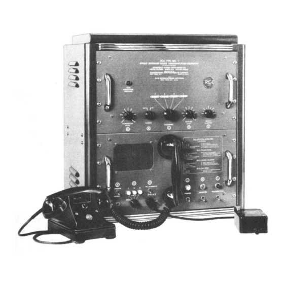
Desk Installation..... . . " ......Frontispiece Comparative Frequency and Power of Type SSB-1 and Equivalent AM System ..6 Cabinet Top Raised and Chassis Withdrawn ........ - Page 8 SINGLE SIDEBAND RADIO COMMUNICATION EQUIPMENT RCA TYPE SSB·l GENERAL DESCRIPTION TECHNICAL SUMMARY TRANSMITTED SIDEBAND ..Lower GENERAL: UNWANTED SIDEBAND ..50 db CHANNELS ....Four SUPPRESSION TYPE OF OPERATION ..Simplex CARRIER SUPPRESSION ..50 db ("Push-to-talk" telephone, or tele...
- Page 9 V -211....RCA-6BA6 ....RF Amplifier V -212 ....RCA-6BE6 ..... 1st Mixer V- 213 ....RCA-6BE6 ..... 2nd Mixer V-214 RCA-6BA6 ....
- Page 10 AM transmitter. S T E A P P L I C A T I AD VANTAGES OF SINGLE The SSB-1 may be used in any of the SIDEBAND, SUPPRES SED following types radio communication CARRIE R CO MMUNICATION.
- Page 13 AF voltage using suitable filters. amplifier, V106B, (one half of a 12AT7 dual The SSB-1 uses three crystal oscillators c.· triode) and a cathode follower, V107A, (also to heterodyne the original modulating signal one half of a 12AT7 tube).
- Page 14 ANTENNA 14249 MODULAT ION NOMINAL MIKE INO AMPL TONE TEST 1000 CPS V·203 6BA6 5 1 KC 251 KC 1401KC 14249 KC NOMINAL MIKE SPEECH BALANCED MECH BALANCED BALANCED INTERMEO AMPL CL IPPER AMPLIFIERS FILTER M OO PWR AMPL V-106(8),V-107(A V·207 V-401-6U8 FL·201...
- Page 15 uses a 6CL6 pentode in a conventional Class R225 and trimmer capacitor C243 are ad A power amplifier circuit having a pretuned justed to balance the output circuit of V207 inductance-capacitance network in the plate to achieve a high order of cancellation of circuit as selected by sections of the CHAN...
- Page 16 • output of V212 thus contains the sum and constant amplitude over the entire frequency • difference frequency components (29,899 kc range. • and 1401 kc respectively). RF interstage T R A N S M I S S I I T H transformer T203, peaked at 1400 kc, passes •...
- Page 17 TRANSMITTER -RECEIVER T-101 METER LINK FILAMENTS V-201 V-106 ---- � V-202 V-203 +600V V-204 V-205 __./ PLATES V-206 V-201 V-207 V-202 FILAMENTS V-101 F-104 FILAMENTS V-102 V-208 V-20 9 OS-101 V -21 0 PLATES V· 21 I MITTER S-1 0 3 V-208 V-212 +150V...
- Page 18 purposes. LOCAL-REMOTE s w i t c h operate the antenna transfer relay (K201). gives selection of either the local handset d. Turning TRANSMITTER switch, S 103, or any one of up to three remote desk sets. on energizes transformers T101 and T102 and lights the TRANSMITTER lamp DS101.
- Page 20 �' CLEARANCE REQUIRED FOR ' ' � WITHDRAWAL OF ANY UNIT � 18 " ., � � " � � �� ooooo �� 21l. " � I I f2 3� WEJGHT-J49LBS Figure 1. Outline Dimensions...
- Page 21 the chassis: i.e., the lowest in channel 1 posi each remote telephone terminal board TB- tion, the next higher in channel 2, etcetera. 501 to terminal boarcJ TB103, mating termi nals bearing identical numbers. These con Install channel crystals as follows: nections are shown in figure 28.
-
Page 22: Location Of Channel Alignment Components On Transmitter-Receiver Chassis
� � � ANT, TERM. � � � � C224 C226 MIXER P L ATE C APACITORS ANTENN A TUNING COIL • C225 C 227 L208 c 205 c 204 � I P A P L ATE TANK 0 4 0 COIL SLUGS �... - Page 23 APPROXIMATE TAP POSITION OF THE APPROXIMATE SLUG POSITION OF IPA PLATE TANK COILS PLATE TANK COIL L - 202 ( Cont'd) CHANNELS 3 or 4 Frequenc y Number of Turns From Number of Turns From Frequency Minimum Inductance Cold End of Coil 5601 and above Serial Nos-5501 -55250 CHANNELS l or 2...
- Page 24 indication below 150 rna, an undercoupled (C-227) for maximum deflection of condition exists. Adjust ANTENNA COUP milliameter. To be sure of tuning to the desired output frequency and not to the os LING CAP 1 (C-201) clockwise in small in crements.
- Page 25 APPROXIMATE SLUG POSITION OF verter equipment is to be used, connect this RECEIVER MIXER GRID COILS equipment to terminal board TB10 4 on the rear apron of the SSB-1 power supply chas Number of Turns Frequency sis as shown in figure 28.
- Page 26 . CONTROl. Cl.ARIFIE:tt TRANSMIT T E R GAIN CONTROi.S O PERATING INSTRUCTIONS I.OUOSPEA!( ! R LOUDSP£AK£R•HANOS£T TRANSFER SWITCH TEi.EGRAPH ICEY TEL.EPHONE ,, . .., Figure 10. front Panel Controls...
-
Page 27: Simplex Radio Telephone Station
Turn TELEGRAPH-PHONE switch All controls and indicators required for ®to PHONE position. Set LOCAL-REMOTE selector @ the operation of the Type SSB-1 are avail able at the front panels of the equipment. to LOCAL position. ® Set SPEAKER-HANDSET switch... - Page 28 (2 positions) At OUT position, SSB-1 operates as a single sideband, suppressed carrier equipment. At IN position, carrier is not suppressed and SSB-1 operates as an AM system with a single sideband. Selects predetermined operating frequency of CHANNEL 1-2-3-4 Rotary switch ©...
- Page 29 0 P E R A T I 0 N. necessary teleprinting equipment ac cessories. The teleprinter itself does the Operation of the SSB-1 for telegraph or switching, from transmit to receive, auto teleprinter such as shown in figure matically. Teleprinter keying speeds being...
- Page 30 C O M PATI BLE WI TH SYST E M. 558-1 SSB-1 TRANSMITTER TRANSMITTER SSB-1 equipment can be operated in RECEIVER RECEIVER any standard AM system by setting CA R RIER switch B to the IN position. TRANSMIT RECEIVE S HUT T I N W N.
-
Page 31: Tube Location Diagram
G E N E R A L. 10 and 80 ohms in series with a transmitting The Type SSB-1 communications equip type mica capacitor of at least 300 uuf. ment should maintain its correct factory b. - Page 33 V204 V205 V206 V207 6CL6 12AT7 V208 1 2AT7 12AT7 V210 6CL6 6BE6 V212 V209 V203 V213 6BE6 V216 6BE6 6BA6 V201 V202 6BE6 12AT7 V215 V211 6146 6146 V214 6BA6 6BA6 6BA6 FRONT PANEL TRANSMITTER RECEIVER CHASSIS VIOl VI 0 2 VI04 VI03 5R4GY...
- Page 34 (top) following alignment procedure de cribes the tuning and adjustment procedures of T-205 for a maximum output. all circuits of the SSB-1. Normally, a (3) Retune the signal generator to ap complete realignment of SSB-1 would proximately 235 kc and increase the ampli...
- Page 35 COIL) required to tune to the desired output (9) To check the overall sensitivity of frequency of channel 1. The required number the SSB-1 connect the signal generator as in of turns relative to the desired frequency is given in Section par.
- Page 36 NOTE: If an audio oscillator is not avail •• (C-240) for half capacitance and turn TRANS able the tone oscillator in the SSB-1 may MITTER GAIN control to zero. be used. Follow channel alignment proce dure as described in Section III, paragraph...
- Page 37 • TABLE TUBE SOCKET VOLTAGES A. READINGS TAKEN WITH VACUUM TUBE VOLTMETER (RCA-WV97A) SYMBOL PIN NUMBERS +630 760 ac 760 ac +630 � - - - 0 � - - � +630 760 ac 760 ac +212 0 _ _ _ _ 400 ac _ _o �...
- Page 38 TABLE 3. TERMINAL BOARD VOLTAGE AND RESISTANCE READINGS. READINGS TAKEN WITH V ACUUM TUBE VOLTMETER (RCA-WV97A) TERMINAL CONDITION TERMINALS BOARD TB-102 KEY UP VOLTAGE 6.3ac 6.3ac 6.3ac +148 +190 +190 +640 KEY DOWN VOLTAGE 6.3ac 6.3ac 6.3ac +148 +190 +190...
- Page 39 cause of the variations, however, certain dif Set the TRA N SMITTER GAIN for a full ferent accessory components are used with output on the channel with the lowest re each of the three type filters. These compo sponse. (This is the channel where the nents are li sted in Table 4 and shown in the TRANSMITTER GAIN control must be most...
- Page 40 Remove C314 and the corresponding terminal to terminal 3 C315 with brackets A201 if FL202 is being (ground). replaced. (3) Set controls on the SSB-1 as Remove old filter unit FL201 follows: FL202. TELEGRA P H-PHONE to PHONE (c) Mount new MFU...
- Page 41 ter is required. The following procedure is is hear at first. recommended. (6) Adjust output of Signal Generator (1) Connect output from an R. F. Sig and Audio Oscillator to give approximately nal Generator through a small coupling capac the same level in the speaker. to Test Point jack TP205 which is at the grid (7) Vary Signal Generator frequency of the 2nd Mixer V213.
- Page 43 •• f· « « « • 18·385 Figure 16. Power Supply, Top View «...
- Page 44 • • • • • • • • • • • • • • • • • • Cl22 R114 Rl23 as6' • Figure 17. Power Supply, Bottom View • • • • • • •...
- Page 45 • • Figure 18. Speech Clipper, Internal View...
- Page 46 • • • • • • • • • • • • • • • • SOTTOM,COVER OPEN 18 1&8 Figure 19. Remote Desk Set • • •...
-
Page 47: Transmitter-Receiver, Top View
V2!6 T205 V215 V213 V214 C251 L 221 L215 V211 L 219 J201 L218 V212 lB-389 figure 20. Transmitter-Receiver, Top View... -
Page 48: Transmitter-Receiver, Bottom View, Location Of Capacitors
• • • C2 3 5 • C257 C253 C230 ·• C255 C229 C228 • • C254 • C288 C23l C232 CR20f CR202. • C22.1 • C2.59 • C261 • C223 C260 C220 C283 C216 C210 C 285 C209 C217 C213 C2.2.2 C21 9... - Page 50 • • • • • • C293 • • • A201 • C3i5 • • • • • • • • • • • • • • • Figure 21C. Transmitter-Receiver, Components Used with Mechanical Filter s , • Equipments Serial Nos. 5601 and above •...
- Page 51 DIRECTIONS- Identify similar component type in the proper column on the lower section of the page. Read across the rows at the top to determine t h e signif icance value of the various colors. COLOR DIGITS RESISTORS C A PACITORS CAPACITORS CAPACITORS DIGITS...
-
Page 52: Slug Position Of Ipa Plate Tank Coils
• ANTENNA LENGTii VS FREQUENCY FOR SINGLE WIRE ANTENNA (SEE PAR. 2 SECTIONm) 11.1 11.1 • <( 11.1 <( • 11.1 • • • • • • FREQUENCY MEGACYCLES 18391 Figure 23. Antenna Length versus Frequency • • • • SLUG POSITI ON OF IPA PLATE TANK COILS •... -
Page 53: Tap Positions Of Plate Tank Coil L-202
�· TAP POSITION OF TANK COIL L-202 (SEE PAR. Bd SEC Cii ::; ; ll.o:: ll.Vl <l 2 CHANNEL 3 a 4 1-o:: :::> CHAN N EL I 62 "- ::;; :::> � 18393 FREQUENCY MEGACYCLES Figure 25. Tap Positions of Plate Tank Coil L-202 RECEIVER GRID C OIL 9�... -
Page 54: Slug Position Of Receiver Mixer Grid Coils
RECEIVER MIXER GRID COIL 9!?_ (SEE PAR SER. NOS.5501 TO 55250 � -- SER. NOS.5601 AND ABOVE � ::::> ::::> � 0� CHANNEL I 8 2 CHANNEL 3 8 4 .=:IE (f) ::IE l!>(/) ::::> z __J ex: (f):::> ::::> FREQUENCY MEGACYCLES IB 395... - Page 55 Stock Number Name and Description Symbol Function TRA N SMITTER RECEIVER UNIT SSB-1 For Serial Noso 5501 to 55250 A201 Mounting filter capacitor For Serial Nos. 5601 to 56200 046-131 For Serial No. 56201 and above 046-132 �cket, Radiomarine Dwg A-1214593.
- Page 58 LIST Cont Reference Locating Number Name and Description Stock Symbol 1::1 Function SSB-1 TRAN S MITTER RE CEIVER UNIT C2S5 V206 balanced modulator Same as Cl05. plate bypass capacitor C2S6 V206 bal anced modulator Same as Cl05. cathode bypass capacitor...
- Page 59 Reference Locating Name and Description Stock Number Symbol Function T R ANS MITTER RECEIVER UNIT SSB-1 067-100 Capacitor, Mica, 1200 uuf, ±10%, 500 Channel 2 crystal C256 feedback capacitor CM30B122K. Same as C256. Channel 1 crystal C257 feedback capacitor V208 coupling capacitor Same as C105.
- Page 60 Cont'd • Reference Locating • Stock Number Name and Description Symbol Function � • • SSB-1 TRA N S MITTER RECEIVER UNIT • • C276A, B,C Bypass Capacitor, Electrolytic, 20-10-20 uf, 350-350-25 v, 077-894 • Sprague Type DFP. • C277 V211 input tuning Capacitor, Mica, 62 uuf, t5%, 500 v, JAN CM20B620J.
- Page 61 PARTS LIST Cont Reference Loca ting Stock Number Name and Description Symbol Function SSB-1 T RAN SMIT T E R RECEIVE R U NIT C306 V216A input capacitor Same as C105. C307 V216A plate bypass Same as C126. capacitor C308 V216B plate bypass Same as C105.
- Page 65 Locating Stock Number Name Description Symbol Fun ction T RANSMITTER RECEIVER UNIT SSB-1 Same as P101 (Not Supplied). P102 Substitute for speech clipper unit Resistor. wirewound, 15,000 ohms, 20 w, Tru-ohm 2'79-797 600 v. power supply R101 bleeder Type Ser-20.
- Page 66 PARTS LISTS Cont Reference Locating Name and Stock Number Description Symbol " Fu nction • • • SSR�1 TRANSMITTER - RECEIVER UNIT R119 Same as Rl13. V107 grid resistor R120 V106 plate resistor Same as R105. • • R121 270-331 V106 cathode resistor Resistor, composition, 330 ohms, ±10%, 1/2 W, JAN RC20BF331K.
- Page 69 LIST Cont Reference Locating Stock Number Name and Description Symbol Functio n � SSB-1 T RA N SMITTER RECEIVER UN IT R239 V208 oscillator plate Same as R238. CR201 / CR202 voltage 276-153 R240 Resistor, composition, 15,000 ohms, ±10%, 2 w, JAN RC42BF153K.
- Page 70 Locating Name and Description Stock Number Symbol Function ::» T R A NS MITTER RECEIVER UN IT SSB-1 R262 V213 oscillator grid Same as R234. resistor R263 V213 cathode resistor Same as Rl37. R264 V213 screen resistor Same as R260.
- Page 72 Refere n ce Locating Name and Description Stock Number Symbol Function • • SSB-1 TRANSMITTER - RECEIVER UNIT • T204 1st IF interstage Transformer, R. F. -262 kc, Automatic Mfg Corp 349-H2 Type 1655-4 with no. 1041 mtg clip. •...
- Page 73 Reference Loca ting Stock Number Name and Description Symbol Function T R A N SMI TTER - R ECEIVER UNIT SSB-1 Same as V106. V205 3-15 me balance modulator Same as V106. 1400 kc balance V206 modulator Same as Vl06.
- Page 74 Reference Loca t4ng Stock Number Name and Description Symbol Function • UNIT T RAN SM ITTER RECEIVER SSB-1 • Same as JlOl. XV201 Mounting for V201 Same as J101. XV202 Mounting for V202 Same as XV108. Mountingfor V203 XV203 Same as XV106.
-
Page 75: Speech Clipper
Reference Locating Stock Number Name and Description Symbol Fun ction SPEE CH C LIPPER SSB-1 V401 screen bypass Same as C105. C401 capacitor 073-554 Capacitor, Ceramic, . 001 uf guaranteed minimum C402 V401 plate coupling value, 500 v, Disc Type. - Page 76 Locating Name and Descr iption Stock Number Symb ol Function REMOTE DESK-SET SSB-1 216-250 Telephone mounting, w/dpst switch, bottom plate and A501 Remote control switch mounting feet, Connecticut Telephone and E lectric Co. assembly Type PL-15110 modified per Radiomarine Dwg C-1241360.
Need help?
Do you have a question about the SSB-1 and is the answer not in the manual?
Questions and answers