
Related Manuals for RCA Radiola 26


Summary of Contents for RCA Radiola 26
- Page 1 Radiola 26 Portable Super-Heterodyne Second Harmonic Instructions Book 5344-A Radio Corporation of America 233 Broadway 10 South LaSalle Street 28 Geary Street New York City Chlcatto, Illinois San Franclaco. California August 1925...
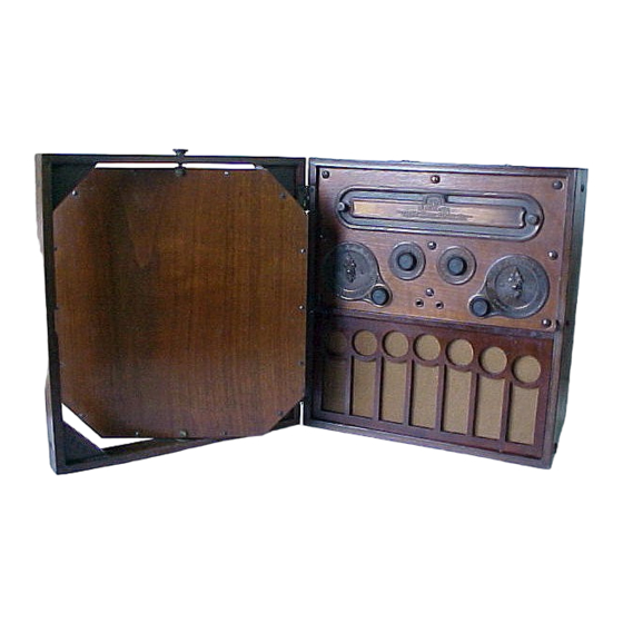
- Page 2 Radiola 26 with Home Battery Box Radiola 26 as a Portable Unit...
-
Page 3: Additional Equipment Required
The Radiola 26 employs six Radiotrons, model UV-199 which are included. Radiola 26, when used in the home, is intended to be placed upon the Home Battery Box which serves as a housing for a set of larger batteries. The larger batteries are strongly recommended for home use, as they provide longer battery life and therefore greater economy. - Page 4 B—Four blocks of 22 ½-volt intermediate size (4 1/8" x 2 9/16" x 2 ¾") "B" battery, connected in series, such as: 4 Eveready No. 768 Plate Batteries, or 4 Burgess No. 5156 Plate Batteries, or 4 Ray-0-Vac No. 5151-BP OR EQUIVALENT C—3 individual "unit cells"...
-
Page 5: Installation
If metal lath is used for all the walls of a room, it may be necessary to place Radiola 26 near a window. This condition is most likely to be met in a modern apartment building or in a modern hotel. - Page 6 Now locate the connection block with five leads extending from its back at the side of the cabinet. One of these leads has a green braid with a yellow tracer and is equipped with a metal tag marked "-A" "+C" and also has a terminal near its middle, while the other end is attached at the upper left edge of the battery compartment.
- Page 7 Fig. 4. Connect the terminal at the end of the lead having yellow braid and red tracer and having a metal tag marked "+A","—B", . 3—Radiola 26 Showing Packing Block in Place "Ground" to the negative (binding post) terminal of battery No. 1. Connect the red wire lead from battery No.
- Page 8 Fig. 4 – Battery connections for Portable Unit 3- 1 ½ V. A Batteries 4- 22 ½ V. B Batteries Fig. 5- Diagram of Battery Connections for Portable Unit...
- Page 9 . 6—Battery Connections When Using Home Battery Box C (Block with -A+C ( Green (Green Tracer) with Yellow T 6-11/2 V.,A Batteries 2-4S V.. B Batteries . 7—Diagram of Battery Connections When Using Home Battery Box...
- Page 10 Radiotrons. Loss of "A" battery voltage through use or age is compensated for by this control. When Radiola 26 is not in use, this control should always be turned as far as possible to the left so that the pointer rests on "Off"...
- Page 11 As the batteries grow older with use, this setting should lie gradually advanced, say week to week, toward "10". . 8—Radiola 26 with Radiotrons in Place The selection of stations is done entirely by manipulating the two "Station Selectors"...
- Page 12 To decrease the volume of signal, turn the "Volume" control toward the left. If no stations are heard the loop of the Radiola 26 should be turned 90 degrees from where it was during the preceding adjustments, and the tuning process just described should be repeated.
- Page 13 CALIBRATION To enable the most satisfactory service to be obtained from tlie Radiola 26, it is desirable to be able to turn to any broadcasting station at will. This can be...
-
Page 14: Maintenance
Radiotrons to the proper temperature, they should be replaced by new ones. The old ones are of no value and should be discarded. The three dry cells provided in Radiola 26 for portable use will give about one-half the operating... - Page 15 life of the larger cells in the Home Battery Box. The longer life batteries should invariably be used for continuous service. There are several indications by which the user may determine that the filament or "A" batteries are becoming exhausted. These are low filament brilliancy, weak signals, and distortion, the signals becoming less and less recognizable.
- Page 16 HOME BATTERY BOX The Home Battery Box for use with the Radiola 26 has two distinct and separate functions. It is designed primarily as a means of holding in a neat and attractive manner a set of larger batteries which will give long and economical service.
- Page 17 This completes the installation of the batteries in the Home 'Battery Box. The cover should then be replaced and fastened down by its screws. Radiola 26 can then be placed in position with the button feet fitting into recesses on the cover of the box and the slot in the bottom of Radiola 26 fitting down over the battery terminal block.
- Page 18 Then hang the loop on the back of the Radiola 26 cabinet, using the little brass knobs at the top and bottom of the loop which slide into catches recessed into the back of the cabinet. Now connect the lead from the antenna to the binding post marked "ANT"...
-
Page 19: Patent Notice
The ground wire should be soldered to the copper ground clamp. Radiola 26 will be operated in the manner previously described and in addition, it will be necessary to regulate the "Station Selector 3". It will be found that signals will come in as usual no matter what the setting of "Station... - Page 21 STATION LOG STATION SELECTORS LOCATION Call Left Hand Right Hand Frequency in Date letters Kilocycles...
Need help?
Do you have a question about the Radiola 26 and is the answer not in the manual?
Questions and answers