
Related Manuals for WAVECONTROL SMP2


Summary of Contents for WAVECONTROL SMP2
- Page 1 Electromagnetic Field Meter SMP2 USER’S MANUAL V 4.0 +34 93 320 80 55 www.wavecontrol.com info@wavecontrol.com Safety, Quality, Service...
- Page 3 Wavecontrol’s knowledge, it is provided with no guarantees of completeness, accuracy, usefulness or timeliness and without any warranties of any kind, express or implied. Wavecontrol provides all content in this document “AS IS” and “WITH ALL FAULTS.” No use of this document or its contents shall be permitted without Wavecontrol’s prior consent.
-
Page 4: Table Of Contents
User’s Manual Electromagnetic Field Meter SMP2 P. 2 Index WARNINGS AND PRECAUTIONS ................4 INTRODUCTION ......................6 FIRST STEPS ......................8 GETTING STARTED ....................10 4.1. Overview ..................... 10 4.2. Field probes ....................12 4.2.1. Connector type ................13 4.2.2. Screw connector ................13 4.2.3. - Page 5 User’s Manual Electromagnetic Field Meter SMP2 P. 3 SMP2 READER SOFTWARE ................... 46 8.1. Installation ....................46 8.2. System requirements ................48 8.3. Using the software ................... 48 8.3.1. Measurements screen ..............49 8.3.2. Screenshots screen ................ 50 8.3.3. Information screen ................. 51 8.3.4.
-
Page 6: Warnings And Precautions
If your equipment has been calibrated according to ISO 17025, the calibration report is valid only for the SMP2 and probe. The probe can, however, be used with any other SMP2. The calibration report will not be valid if you switch the probe. - Page 7 User’s Manual Electromagnetic Field Meter SMP2 P. 5 Environmental information Disposal of your old product: Your product is designed and manufactured with high quality materials and components, which can be recycled and reused. When this crossed-out wheeled bin symbol is attached to a product it means the product is covered by the European Directive 2002/96/EC.
-
Page 8: Introduction
(FFT), including % direct EMF exposure assessments to limit lines by using the weighted peak method (WPM). We have developed the SMP2 to meet the needs for personal safety assessment in connection with exposure to electromagnetic fields. Its... - Page 9 The data stored in the memory can be easily downloaded to a computer via a USB or fibre optics port for later processing. The SMP2 is also available with a built-in GPS receiver (optional) to allow each measurement to be associated automatically with the geographic location where it was taken.
-
Page 10: First Steps
User’s Manual Electromagnetic Field Meter SMP2 P. 8 3. FIRST STEPS This section contains instructions for unpacking and checking the equipment when you receive it. Compartment for USB cable, f.o. cable (optional), documents, etc. Field Probe SMP2 (and battery charger below) - Page 11 User’s Manual Electromagnetic Field Meter SMP2 P. 9 2. Check that all the components of the SMP2 are there. The SMP2 is delivered in a compact briefcase that should contain the following components: • SMP2. • 1 or more electromagnetic field probes.
-
Page 12: Getting Started
User’s Manual Electromagnetic Field Meter SMP2 P. 10 4. GETTING STARTED 4.1. Overview The front panel of the SMP2 contains the user interface, made up of the screen and keypad. The keyboard presents 8 standard buttons, 4 virtual buttons (below the screen) and 1 ON/OFF button. - Page 13 (measuring screen). allows to get back to an earlier menu or to cancel a selection. allows to take print-screens anytime. The top of the SMP2 holds the field probe connector. Probe connector ON/OFF button Integrated GPS...
-
Page 14: Field Probes
User’s Manual Electromagnetic Field Meter SMP2 P. 12 The bottom of the SMP2 holds the other connections of the equipment. Mini USB connector Charger connector Tripod ¼’ screw Fibre optic connector Figure 4: Bottom • Mini USB connector and fibre optics: allows connection to a PC in order to: •... -
Page 15: Connector Type
User’s Manual Electromagnetic Field Meter SMP2 P. 13 4.2.1. Connector type There are two types of connector: push-pull and screw. Figure 5: Push-pull connector Figure 6: Screw connector 4.2.2. Screw connector 4.2.2.1. How to connect the field probe Connect the field probe by inserting the male connector into the female connector with the tab aligned. -
Page 16: Push-Pull Connector
4.3. External connections 4.3.1. USB A USB to mini USB cable is delivered with the SMP2. After installing the SMP2 software (first install the software see 8.1) just plug the cable to the SMP2 and to the computer. You will be able to download stored measurements to the computer or update the SMP2 firmware. -
Page 17: Fibre Optic
User’s Manual Electromagnetic Field Meter SMP2 P. 15 4.3.2. Fibre optic A fibre optic link is available as an option in order to remotely control and see live readings of the instrument from a PC without interfering with the measurements. -
Page 18: Smp2 - Initial Use
• Storage of results in memory. Several additional functions make the SMP2 a very complete field measurement system. The SMP2 is controlled via the keypad and easy access to data is available through the different settings. 5.1. Switching the apparatus on and off The apparatus is switched on and off with the ON / OFF button located on the upper part of the keyboard. -
Page 19: Main Screen
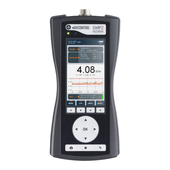
User’s Manual Electromagnetic Field Meter SMP2 P. 17 5.2. Main screen The main screen provides instantaneous and continuous information on the electromagnetic field being measured. Battery Icons Date and time Probe information Measurement information Field information (Double value display) Graph... - Page 20 4. Logging time. Field information: (updated twice per second) The SMP2 has a double screen display. Depending on the probe selected, you have the RMS and Peak values or RMS and Average values. • Total field: instantaneous total field level.
- Page 21 User’s Manual Electromagnetic Field Meter SMP2 P. 19 Maximum, minimum and average values: these values (below the total field values) are initialized when beginning a new log or can also be initialized with the virtual button “Reset”. Average value is updated depending on the type of averaging and interval chosen in the Measurement Options.
-
Page 22: Menu Screen
User’s Manual Electromagnetic Field Meter SMP2 P. 20 • Units: change the current units (this will reset the min, max, average and graph). With the up and down arrow you can select the unit. By pressing OK the highlighted unit will be selected. -
Page 23: Measurement Options Screen
User’s Manual Electromagnetic Field Meter SMP2 P. 21 5.4. MEASUREMENT OPTIONS screen This screen is used to configure different parameters related to measurement behaviour. It appears as a menu with a scrolling bar. The parameters to be configured are shown on the left and the different options for each parameter are shown on the right. - Page 24 User’s Manual Electromagnetic Field Meter SMP2 P. 22 The following parameters can be configured: HF BROADBAND QUICK SET-UP • Standard: List of preselected standards. This will affect other parameters that will not be editable. For example: if you choose ICNIRP standard then all the parameters in “MEASUREMENT BEHAVIOUR”...
- Page 25 User’s Manual Electromagnetic Field Meter SMP2 P. 23 • Average interval: used to select the time interval for calculation of the average. The available intervals are 10 s, 15 s, 30 s, 1 min, 2 min, 5 min, 6 min, 10 min, 15 min and 30 min.
- Page 26 When performing, for example, a 6-minute average measurement, this last sample screenshot will show the final average result. This image will be available for reporting with the SMP2 Reader software. • Save measurement name: permits to save a name for each measurement.
-
Page 27: Measurement Log Screen
User’s Manual Electromagnetic Field Meter SMP2 P. 25 5.5. MEASUREMENT LOG screen This screen shows all the available From this menu you can use measurements. The arrows are the “VIEW” virtual button to used to select the next measurement view a specific measurement or the preceding measurement. - Page 28 User’s Manual Electromagnetic Field Meter SMP2 P. 26 When a measurement is entered, you can view a measurement summary screen. To view the data, use the “VIEW DATA” virtual button. To view the screenshots taken during the measurement press on “LIST IMAGES”...
- Page 29 User’s Manual Electromagnetic Field Meter SMP2 P. 27 Use the QR virtual button to obtain the QR code which can be scanned using a QR scanner or reader to obtain information about the measurement results (Date and time of measurement, type of value (RMS,...
-
Page 30: Probe Information
User’s Manual Electromagnetic Field Meter SMP2 P. 28 5.6. Probe information This screen allows you to see information about the probe, activate or deactivate the calibration warning and configure calibration details in case of 3rd party calibration. When your calibration is less than a month to expire, you will notice a colour indication in the probe information bar. - Page 31 User’s Manual Electromagnetic Field Meter SMP2 P. 29 In calibration options, the warning can be disabled by selecting ‘No’ in the option Calibration warning, remove the screen message by clicking any button on the SMP2. If the user choses to use an external calibration, a new calibration date can be inserted and validity can be set by enabling 3rd party calibration.
-
Page 32: Gps Screen
User’s Manual Electromagnetic Field Meter SMP2 P. 30 5.7. GPS screen This screen has the same layout and behavior as the MEASUREMENT OPTIONS screen. It allows to modify the GPS parameters. Those parameters are: • Format: allows to select 3 standard format for the latitude and longitude. You can choose between: •... -
Page 33: Settings Screen
User’s Manual Electromagnetic Field Meter SMP2 P. 31 5.8. SETTINGS screen This screen has the same layout and behavior as the MEASUREMENT OPTIONS screen. It allows to modify the general parameters of the SMP2. The following parameters can be configured:... - Page 34 (Activity may be communicating with PC, keyboard pressing key). When log is activated, automatic turn off is disabled. • System info: indicates the version of the SMP2 software. By clicking on OK, you will have more information about the unit like disk space available.
-
Page 35: Functions
User’s Manual Electromagnetic Field Meter SMP2 P. 33 6. FUNCTIONS This section describes the main functions of the SMP2, in addition to instantaneous measurement of the electromagnetic field. 6.1. Measurement modes There are several working modes, depending on the probe being used. All probes have the time mode (6.1.1) with spatial average... -
Page 36: Time Domain Measurement
User’s Manual Electromagnetic Field Meter SMP2 P. 34 6.1.1. Time domain measurement If you are using a broadband probe, this is the default mode. If you are using a selective probe, select this mode on the main screen virtual menu (‘MORE…’ ‘MODE’ ‘Time’). - Page 37 To store position information along with the field values, the GPS receiver must be enabled before logging is started. Note 1: During logging, the parameters of the SMP2 cannot be changed. Note 2: With the broadband probes, if you select a limit you can go to the ‘UNITS’...
- Page 38 User’s Manual Electromagnetic Field Meter SMP2 P. 36 • It will log samples for [Measurement time] minutes. • The measurement will stop automatically and the alarm will sound. The device will calculate the average, display it on the screen and store the data in the memory.
-
Page 39: Fft Mode - Frequency Domain Measurements
User’s Manual Electromagnetic Field Meter SMP2 P. 37 6.1.2. FFT mode - frequency domain measurements This function is only available with a selective probe, such as the WP400, WP400-3 or the WPH-DC. Frequency domain measurements contain frequency information on the analysed field, obtained through calculation of the FFT of the signal. - Page 40 User’s Manual Electromagnetic Field Meter SMP2 P. 38 In frequency mode the parameters of the “MEASUREMENT OPTIONS“ menu have no effect. All parameters have to be chosen from the virtual menu of the main screen: • ”MODE”: Time, FFT or Freq. log (see section 6.1).
- Page 41 User’s Manual Electromagnetic Field Meter SMP2 P. 39 Note: If data is downloaded to a PC, the FFTs for all the axes and the total field can be displayed in a single graph. To save an FFT, go to the main screen (direct access available by pressing the “Home“...
- Page 42 User’s Manual Electromagnetic Field Meter SMP2 P. 40 • If you only need to check compliance in % of a standard, the time mode is suitable. This will give a complete and instantaneous result as a % of the limit.
-
Page 43: Single Frequency Time Mode
User’s Manual Electromagnetic Field Meter SMP2 P. 41 6.1.3. Single frequency time mode In this mode, a log is kept of the changes in a single frequency over time. An example is shown in the figure above. There are two... -
Page 44: Spatial Average
User’s Manual Electromagnetic Field Meter SMP2 P. 42 6.1.4. Spatial average Activate this option through MENU MEASUREMENT OPTIONS Spatial average. This mode can be used along with the Time mode and the Frequency Log mode. With this mode you can automate the process if you need to take several measurements at different positions. -
Page 45: Alarm
6.3. GPS The SMP2 has a built-in state-of-the-art GPS that allows it to display and memorize the position of the device when taking measurements. The incorporation of ublox functions makes the receiver highly sensitive and accurate, allowing exact positioning even in areas with poor satellite visibility. -
Page 46: Battery Information
7. BATTERY information 7.1. General information The SMP2 includes a rechargeable Li-ion battery allowing the device to run for over 20 hours (in selective mode that time is reduced to just over 6.5 hours). You can check the battery charge level at any time in the upper right-hand corner of the main screen. -
Page 47: Recharging
The procedure is as follows: • Plug the charger into an electrical outlet (110-240 V AC). • Connect the charger to the SMP2. The red LED will light up. If it does not light up, the charger is not properly connected. - Page 48 Before connecting the SMP2 to your PC, run the Setup file. During the process the Setup file will install the software and all the necessary drivers. When the installation is complete, connect the SMP2 and Windows will install the drivers automatically. The following images show the full process:...
- Page 49 User’s Manual Electromagnetic Field Meter SMP2 P. 47 Figure 11: Installation of the program...
- Page 50 • RAM: 2 GB. 8.3. Using the software When running the software and connecting the SMP2 for the first time, a pop- up window will open to allow you to register to the Wavecontrol intranet. This is required for free software and firmware updates (see chapter 9 for updates and appendix 8 for the intranet).
- Page 51 Measurements are loaded automatically when the SMP2 is connected by USB. A list will appear on the left with the measurements stored in the SMP2. When you select a measurement, a table and a graph will appear on the right with all the field samples taken.
- Page 52 Note: Only measurements with 6-minute averages are compatible with this function. 8.3.2. Screenshots screen In this tab you can display and download SMP2 screenshots. Select a measurement from the list to view the associated screenshots. Each line contains: a selection box, the date of the screenshot and the sample reference.
- Page 53 User’s Manual Electromagnetic Field Meter SMP2 P. 51 8.3.3. Information screen This tab shows internal SMP2 information, such as the firmware version, storage capacity, and so on. Figure 13: SMP2 software information screen 8.3.4. Exporting spreadsheets On the Measurements screen you can click on “Export” to start downloading and exporting to an Excel file.
- Page 54 User’s Manual Electromagnetic Field Meter SMP2 P. 52 Figure 14: SMP2 Export parameters In the exported report, the “Report” tab of the page format report shows the main data of the measure, the associated graph, the GPS position with a map, and the final screenshot (if any), depending on the configuration (see figures 14 and 15).
- Page 55 8.3.5. Control centre screen If you have access to a Wavecontrol Control Centre for managing MonitEM and SMP2 devices, you can upload your SMP2 measurements directly to the Control Centre. Note: You can only upload one measurement at a time. You will need an Internet connection to use this feature.
- Page 56 This screen is only available with a fibre optic connection (see section 4.3.2). It provides a real-time display on your PC screen of the data being measured by the SMP2. It also allows you to change settings for the device, such as: • Measurement mode (time, frequency or time at one frequency).
- Page 57 Note: With the Control button pressed, you can also use the arrows on the keyboard to move the cursor on the graph in the same way as the arrows of the SMP2 keypad. When the GPS is switched on with a fixed position, a map will show the position of the SMP2 (this requires an Internet connection).
- Page 58 Home login, and enter your login and password. You will be directed to the download page. Once in the download page, click on SMP2 SMP2 software. Download and install the file: SMP2_software.zip. 9.2. SMP2 firmware update Please follow these steps: 1.
- Page 59 User’s Manual Electromagnetic Field Meter SMP2 P. 57 If the latest version of the firmware or expansion board firmware was delivered to you by hand, you can update it by: • Following steps 1 to 3, • going to Tools Update Update Firmware (or Update Expansion Board Firmware), and •...
- Page 60 User’s Manual Electromagnetic Field Meter SMP2 P. 58 Note 2: In case the SMP2 cannot be connected to the mains, please be sure there is enough battery. Note 3: It is recommended to update the firmware without any field probe connected...
- Page 61 Maintenance by the user is limited to the outside of the device, its connections and management of regular calibrations. Any maintenance or repair for which the device needs to be opened must be carried out by Wavecontrol to avoid invalidating the warranty.
- Page 62 User’s Manual Electromagnetic Field Meter SMP2 P. 60 To recalibrate your equipment, please contact your local distributor or Wavecontrol at service@wavecontrol.com. Wavecontrol offers ISO 17025 accredited calibrations at its LabCal Wavecontrol laboratory. We are aware of the importance of recalibration to the management of your operations.
- Page 63 If the problem persists after 2 – 3 trials, contact your local distributor or Wavecontrol directly at service@ wavecontrol.com. I try to enter the menu and the SMP2 This happens because your SMP2 returns to the main screen every time. reader is on Live measurement. Exit live measurement and you will be able to enter the menu.
- Page 64 User’s Manual Electromagnetic Field Meter SMP2 P. 62 12. TECHNICAL SPECIFICATIONS Measurement Functions Measurement feld probes Interchangeable; automatic probe detection and recognition system Measurement units V/m, kV/m, µW/cm , mW/cm , W/m , A/m, nT, µT, mT, T, mG, G, %...
- Page 65 User’s Manual Electromagnetic Field Meter SMP2 P. 63 GPS (optional) Chip set 56-channel u-blox 7 engine, embedded Position accuracy Position 2.5 m CEP / 4.0 m Sensitivity Tracking: –162 dBm / –158 dBm SBAS (Satellite Based WAAS/EGNOS/MSAS support Augmentation System)
- Page 66 User’s Manual Electromagnetic Field Meter SMP2 P. 64 Appendix 1. Available probes The SMP2 has a wide range of probes that make it adaptable to every sector and application. They include probes for the electric field, magnetic field, electric and magnetic fields, low or high frequencies, high sensitivity or high power, broadband or selective.
- Page 67 In order to get the most out of your SMP2, it is important to choose the proper configuration, so that it will be suitable to the characteristics of the field to be measured.
- Page 68 User’s Manual Electromagnetic Field Meter SMP2 P. 66 Resistance and Magnetic 0 - 10 MHz, EN 50505 • Broadband arc welding fields. pulsed measurement IEC/EN 62822-1 and weighted IEC/EN 62822-2 measurement. IEC/EN 62822-3 • Probes: IEEE Std C95.1 WPH-DC, IEEE Std C95.3.1...
- Page 69 User’s Manual Electromagnetic Field Meter SMP2 P. 67 EAS/ RFID Magnetic LF: 1Hz – EN 50364 • Broadband fields. 500 kHz measurement IEC/EN 62369-1 and weighted MF: 2-30 MHz IEEE Std C95.1 measurement. HF: few GHz IEEE Std C95.3 • LF: WP400 IEEE Std C95.3.1...
- Page 70 If it is found that the field is close to 30 mT, where the SMP2 will be placed to take the final measurement, precautions should be taken to prevent the SMP2 from moving, or using the extension cable as mentioned previously.
- Page 71 • Position the tip of the probe in the Zero Gauss chamber. • Press the “Zero” button in the SMP2 menu. • Repeat these last 2 operations each time you want to compensate for any...
- Page 72 User’s Manual Electromagnetic Field Meter SMP2 P. 70 Range: selects the behavior of the measurement range of the probe. • Auto: range will increase and decrease depending on the field to be measured. • Auto-increasing: range will only increase. This is important when measuring sporadic peaks.
- Page 73 User’s Manual Electromagnetic Field Meter SMP2 P. 71 Appendix 4. Low frequency assessment Introduction The SMP2 + WP400 or WP400-3 field probe combination is the most complete and compact available on the market for evaluation of human exposure to low frequency electromagnetic fields. It allows evaluation of the electric field (E) and the magnetic field (H) using a single probe, over a frequency range of 1 Hz to 400 kHz.
- Page 74 User’s Manual Electromagnetic Field Meter SMP2 P. 72 Measurement methods The SMP2 + any of the selective field probe (WP400, WP400-3 or WPH-DC) combination allows you to choose any of 3 measurement methods. 1. Broadband measurement Broadband measurements may be made of the electric field (E) and the magnetic field (H).
- Page 75 Screenshot 1F 2. Selective measurement (FFT) The SMP2 + WP400 (or WP400-3 or WPH-DC) allows you to make selective measurements by means of real-time FFT-based signal analysis using digital signal processing techniques. This can be done for both the E field and the H...
- Page 76 User’s Manual Electromagnetic Field Meter SMP2 P. 74 First of all, select the “FFT” option on the “MODE” (screenshot 2A). The spectrum then appears on the SMP2 display. You may now select the desired span (screenshot 2B). If you then press “LOG” on the dynamic menu, the FFT of the signal will be saved, which displays information about the limit selected, span, max hold duration and filter (screenshot 2C).
- Page 77 User’s Manual Electromagnetic Field Meter SMP2 P. 75 • Select the “Freq. log” mode directly on the “MODE” menu, then specify the desired frequency (screenshot 3C). Screenshot 3A Screenshot 3B Screenshot 3C...
- Page 78 With the limit chosen, you can assess the EMF by ensuring that both the peak and the RMS value are below 100%. Please note that the Peak value, given by the SMP2, is already divided by Square of 2 for a direct reading to comply with the limits.
- Page 79 User’s Manual Electromagnetic Field Meter SMP2 P. 77 Screenshot 4A Screenshot 4B...
- Page 80 User’s Manual Electromagnetic Field Meter SMP2 P. 78 Simplified block diagram of RMS-Peak-FFT analysis for the WP400 and WP400-3 probes 1 M Samples/s for SPAN 400 kHz 100 k Samples/s for SPAN 40 kHz Real time 10 i 10 k Samples/s...
- Page 81 User’s Manual Electromagnetic Field Meter SMP2 P. 79 Special functions of the WP400 and WP400-3 probes These probes have certain specific functions, given their spectral analysis capacity. • RANGE: Select how the probe will adapt to field levels. With changes in levels, the electronics processing the signal must adapt to high or low levels in order to give accurate results under both conditions.
- Page 82 User’s Manual Electromagnetic Field Meter SMP2 P. 80 • 100 Hz (-3dB at 100 Hz, < -18dB at 50Hz). Useful for attenuating the signal at 50/60 Hz. Gives a better signal-to-noise ratio for measuring harmonics in mains or measuring weak signals at high frequencies without the fundamental overloading the dynamic range.
- Page 83 User’s Manual Electromagnetic Field Meter SMP2 P. 81 Appendix 5. Radar measurements The high frequency field probes with the fast option have a special feature called Max Fast RMS. It can be activated on the main screen with the “MODE” button.
- Page 84 Appendix 6. E-field Measurement under Powerline When measuring electric field below a power line, it is advisable to place the SMP2 in horizontal and and be separated from the unit with a tripod or a wood stick or extension. In high frequency measurements, placing the device horizontally will increase the LF (low frequency) immunity and obtain more accurate results.
- Page 85 Format of commands and responses Communication is done through the exchange of strings with the XML format. The SMP2 checks the frames received and rejects them if not well formed. The XML format accepted by the SMP2 parser is as follows:...
- Page 86 “ " & & ‘ ' < < The XML format used by SMP2 is as follows: Response: General format of the correct reply PC SMP2 <?xml version=”1.0” encoding=”ISO-8859-1”?> <reply> <result> <instruction>[String that identifies the command]</instruction> [Specific results of the command] </result>...
- Page 87 User’s Manual Electromagnetic Field Meter SMP2 P. 85 Commands and responses Instruction Parameters Response GET_SAMPLE field_type: 0 electric, 1 magnetic get the field value: field in V/m or uT measured unit: units displayed on the screen (see Units section) x, y, z: field in axis...
- Page 88 GET_FFT (SET_DATA_TYPE has to be in FFT mode first) Units Below it is described in c# the units of SMP2 with the identification number that the command GET_SAMPLE returns. typedef enum E_FIELD_V_m = 0, /* E - V/m...
- Page 89 User’s Manual Electromagnetic Field Meter SMP2 P. 87 Limitations and Timeout The XML commands from the PC to the SMP2 can be up to 32768 bytes. The SMP2 expects to receive complete commands in less than 3 seconds (counting from the time of receipt of the first byte); If after this time it does not have a full and valid response, an error message is sent and discards the information received so far.
- Page 90 User’s Manual Electromagnetic Field Meter SMP2 P. 88 Example c# code to generate the MD5 using System; using System.text; using System.Security.Cryptography; private string AddMd5(string cmd) String formatted_xml = cmd; String result = string.Empty; string[] string_parts; /* Add a <md5>MD5_VALUE</md5> tag before the closing </cmd> tag. */ (!formatted_xml.Contains(“<md5>”))
- Page 91 One of the important things that you can do via the intranet is keep your SMP2 device always up to date. Wavecontrol offers you regular updates of the SMP2 firmware and the SMP2 Reader software, free of charge.
- Page 92 User’s Manual Electromagnetic Field Meter SMP2 P. 90 Appendix 9. Additional SMP2 Accessories There are optional items which could be requested additionally with the standard accessories mentioned in section 3: Accessory Part number GPS (internal) WSNO0001 Non-reflective wooden tripod + transport cover...
- Page 93 User’s Manual Electromagnetic Field Meter SMP2 P. 91 DECLARATION OF CONFORMITY (DoC) Manufacturer: Wavecontrol, S.L. C/ Pallars, 65-71 · 08018 Barcelona (Spain) Object of the declaration: SMP2 Electromagnetic Field Meter The above mentioned product complies with the essential requirements, which are specified in the 2004/108/EC Directive on the approximation of the laws of the Member States relating to electromagnetic compatibility.
- Page 94 User’s Manual Electromagnetic Field Meter SMP2 P. 92 • IEC-EN 61000-4-5:2007 + CORR:2010 Testing and measurement techniques - Surge immunity test. • IEC-EN 61000-4-6:2009 Electromagnetic compatibility (EMC) -- Part 4-6: Testing and measurement techniques - Immunity to conducted disturbances, induced by radio- frequency fields.
- Page 96 www.wavecontrol.com...
- Page 97 Safety, Quality, Service +34 93 320 80 55 www.wavecontrol.com info@wavecontrol.com...
Need help?
Do you have a question about the SMP2 and is the answer not in the manual?
Questions and answers