
Subscribe to Our Youtube Channel
Related Manuals for WAVECONTROL SMP2


Summary of Contents for WAVECONTROL SMP2
- Page 1 Electromagnetic Field Meter SMP2 USER’S MANUAL V1.21 +34 93 320 80 55 www.wavecontrol.com info@wavecontrol.com Safety, Quality, Service...
-
Page 2: Table Of Contents
4.2.3 Push-pull connector ............11 4.3 External connections ..............12 4.3.1 USB ..................12 4.3.2 Fibre optic ................12 SMP2 – INITIAL USE ................13 5.1 Switching the apparatus on and off .........13 5.2 Main screen ..................13 5.3 Menu screen .................16 5.4 Measurement Options screen ..........16 5.5 Measurement Log screen ............18... - Page 3 10.3 Periodic recalibrations ............33 TECHNICAL SPECIFICATIONS ............34 WARRANTY ..................35 ANNEX 1. WP400 PROBE SPECIAL FUNCTIONS ....... 36 ANNEX 2. WPF18 PROBE SPECIAL FUNCTIONS ....... 38 ANNEX 3. COMMUNICATION PROTOCOL ........... 39 DECLARATION OF CONFORMITY (DOC) ..........45 www.wavecontrol.com P. 3...
- Page 4 User’s Manual Electromagnetic Field Meter Congratulations for your acquisition of a Wavecontrol SMP2. This Manual provides you with instructions for using and handling your SMP2. Please read this Manual carefully before using your SMP2. www.wavecontrol.com P. 4...
-
Page 5: Warnings And Precautions
European Directive 2002/96/EC. Your SMP2 is not watertight and it should be Please get informed about the local separate protected from moisture, such as rain. collection system for electrical and electronic products. -
Page 6: Introduction
The SMP2 has been developed to meet demanding customer requirements in the RF safety The SMP2 is also available with a built-in GPS measurements domain. Its versatility makes it receiver (optional) to allow each measurement to... -
Page 7: First Steps
• USB – mini USB cable. delivery note before you sign it. • Fibre optic link (optional). 2) Check that all the components of the SMP2 are there. The SMP2 is delivered in a compact If any of those components is missing, please briefcase that should contain the following contact Wavecontrol. -
Page 8: Getting Started
Electromagnetic Field Meter 4. GETTING STARTED 4.1 Overview The keyboard presents 8 standard buttons, 4 The front panel of the SMP2 contains the user virtual buttons (below the screen) and 1 ON/OFF interface, made up of the screen and keypad. button. - Page 9 LED should be always on. • Light sensor: allows to control the automatic screen back-light intensity depending on ambient light. The bottom of the SMP2 holds the other connections of the equipment. Mini USB connector Charger connector Tripod ¼’ screw...
-
Page 10: Field Probes
• Mini USB connector and fibre optics: allows 4.2.1 Connector type connection to a PC in order to: There are two types of connector: push-pull and • Download data stored in the SMP2 memory. screw. • Update firmware for the equipment. • Control the unit remotely. -
Page 11: Screw Connector
The polarity of the connector must be observed probe firmly with one hand (pulling with the thumb) and so the red marks on the male and female. while you hold the SMP2 with your other hand as connectors must line up. shown in the pictures below:... -
Page 12: External Connections
A USB to mini USB cable is delivered with the SMP2. After installing the SMP2 software (first install the software see 8.1) just plug the cable to the SMP2 and to the computer. You will be able to download stored measurements to the computer or update the SMP2 firmware. -
Page 13: Smp2 - Initial Use
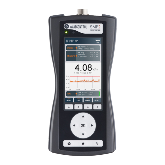
The main screen provides instantaneous and continuous information on the electromagnetic The SMP2 is controlled via the keypad and easy field being measured. access to data is available through the different • Date and time: date and time of the apparatus. - Page 14 Measurement Options. • Logging and average parameters: 1. Average window time. • The sum of each axis field (for power density 2. Type of interval (sliding or arithmetic). units): 3. Logging time. www.wavecontrol.com P. 14...
- Page 15 This information is only displayed when the GPS is switched on. • Lat: latitude. • Lon: longitude. On the right side a colour indicates the quality of the position: • Red: bad. • Orange: average. • Green: good. www.wavecontrol.com P. 15...
-
Page 16: Menu Screen
• Measurement log (allows to see the stored measurements). • GPS (allows to change GPS parameters). • Settings (allows to change general parameters of the unit). • Messages. (in case some events are available this menu will appear). www.wavecontrol.com P. 16... - Page 17 (or minutes). The available intervals are parameter will show as “Not available”, since 0.5s, 1s, 5s, 10s, 15s, 30s, 1min and 6min. it is not compatible with that selected mode. www.wavecontrol.com P. 17...
-
Page 18: Measurement Log Screen
OK on the selected point. image with the 6 min average results. This image will be available to be exported directly into the report with the SMP2 software. 5.6 GPS screen • Save measurement name: permits to save This screen has the same layout and behavior a name for each measurement. -
Page 19: Settings Screen
0 and the maximum of the automatic turn off is disabled. measurement or between the minimum and • System info: indicates the version of the SMP2 maximum to have a precise view of the time software. By clicking on OK, you will have variation of the field. -
Page 20: Functions
In order to store positioning information along with the measurements field values, the GPS receiver should be enabled before One of the functions of the SMP2 is the storage logging is started. of measurements in memory for later study 6.1.1.1 Measurements according to ICNIRP or processing. -
Page 21: Fft Mode - Frequency Domain Measurements
Standard. All the parameters will be forced to the measurement contains 401 frequency points so pre-defined value: the memory of the SMP2 allows storage of up to 1000 frequency measurement. 1. The apparatus will wait 10 s before starting the measurement to allow the technician Note: in this mode you can see the FFT on the graph to move away. - Page 22 You will get an FFT showing the 50 Hz and its main harmonics in the frequency domain (from 1 to 400 Hz). Repeat this for electric and magnetic Note: When downloaded to the PC, all axis of FFT field. measurements can be seen on the graph. www.wavecontrol.com P. 22...
-
Page 23: Log Frequency Log Mode
10 Hz, then change the filter to 1 Hz. In this case always measure with the SMP2 on a tripod and the fibre link in order to avoid any external perturbation. • We also recommend start using the higher In this mode, the unit will display the temporal span. -
Page 24: Spatial Average
When launching a log, it will start by measuring the first point. At the end of each measurement, a pop-up will ask whether you want to do a new point, repeat the last point or finalize the spatial average. www.wavecontrol.com P. 24... -
Page 25: Alarm
6.4 GPS Note: enabling the GPS increases power consumption The SMP2 is available with a built-in latest- and reduces its autonomy. It is important to keep it generation GPS ublox engine 7 allowing you to... -
Page 26: Battery Information
The battery charge time is 4–5 hours. We Li-ion batteries have no “memory effect”, so recommend to turn off the SMP2 for charging the there is no need to fully discharge the battery. It is battery. The procedure for charging the battery is: recommended to charge completely the battery before the first use. -
Page 27: Software
Electromagnetic Field Meter 8. Software 8.1 Installing the software Before connecting the SMP2 to the PC, launch the When the installation is finished you can connect setup file (available in the USB flash key). the SMP2, Windows will install the driver automatically. -
Page 28: System Requirements
User’s Manual Electromagnetic Field Meter 8.2 System requirements the SMP2 is connected by USB. A list on the left • Operating system: Minimum Windows 7. will appear with all the current measurements. • RAM: 2 GB. When clicking on a measurement, a table and a •... -
Page 29: Screenshots Screen
8.3.2 Screenshots screen the + sign above all the selection boxes. This tab allows to download and display SMP2 screenshots. Click one line to be able to see the When pressing the “Export selected” button the screenshot. -
Page 30: Control Centre Screen
8.3.5 Control centre screen If you have access to a Wavecontrol Control Center for the management of MonitEM and SMP2 units, then you can upload your SMP2 measurements directly to the Control Center by using SMP2 software. Note: you can only upload a measurement at a time. -
Page 31: Live Screen
“Send to control centre”. It will show link (see 4.3.2). It provides a real time display of the data being measured by the SMP2 and you a new tab (fig 16), where you can: allows to modify some of its parameters. -
Page 32: Firmware Updating
SMP2 firmware can be updated from the SMP2 Note1: this is quite a long process (from 10 to 20 software. minutes). To update it connect the SMP2 to the PC via USB SMP2 Note2: be sure that the has enough battery. -
Page 33: Maintenance
This section explains the maintenance of the apparatus that can be carried out by the user. If The SMP2 and its field probes are not watertight. you have any questions about how to maintain When using them outdoors be sure to protect the the SMP2, please contact Wavecontrol. -
Page 34: Technical Specifications
-10 ºC a +50 ºC Size (without field probe) 100 x 215 x 40 mm Weight (without probe) 610 g (including the internal GPS receiver) Hardcase, battery charger, USB-mini USB cable, Accessories SMP2 Reader software, user manual, probe calibration certificate www.wavecontrol.com P. 34... -
Page 35: Warranty
In order to obtain service under this warranty, the WAVECONTROL customer must notify Wavecontrol (or one of its Pallars 65-71 distributors) of the defect before the expiration of E-08018 Barcelona the warranty period, by sending a Failure Report... -
Page 36: Annex 1. Wp400 Probe Special Functions
• 10 Hz (-3dB at 10 Hz) Recommended if you are is important when measuring sporadic peaks sure that no signal below 10Hz is present (most because even when field is low, SMP2 will be of the cases). ready for the next peak to be measured. This option should be used when single peaks occur •... - Page 37 Electromagnetic Field Meter Below you can find 2 images with this filter response. Figure 19: Filter response when a limit is applied (For limit see 6.2) Figure 20: Filter response when no limit is applied (For limit see 6.2) www.wavecontrol.com P. 37...
-
Page 38: Annex 2. Wpf18 Probe Special Functions
• Normal RMS: allows standard measurement of the total RMS field • Max fast RMS: allows measurement of the maximum RMS field over a very short integration time (4 ms). The maximum measured RMS value is displayed every 0.5s. www.wavecontrol.com P. 38... -
Page 39: Annex 3. Communication Protocol
Ports USB: it emulates a serial port service with CDC, The XML format accepted by the SMP2 parser is automatically negotiated rate, 8 bits, no parity,1 as follows : bit stop. The Vendor ID and Product 0x1FC9 ID 0x807B of the USB may be used to find the port number opened by the driver. - Page 40 “ " & & ‘ ' < < The XML format used by SMP2 is as follows: Response: General format of the correct reply PC SMP2 <?xml version=”1.0” encoding=”ISO-8859-1”?> <reply> <result> <instruction>[String that identifies the command]</instruction> [Specific results of the command] </result>...
- Page 41 YYYY-MM-DD YYYY-MM-DD HH:mm:ss HH:mm:ss set time INFO_SYSTEM device: identify device SMP2 get info about device serial_micro: unique ID of micro crontoler firmware_version: firmware version serial_device: device serial number hardware_version: hardware version MEASURE_START...
- Page 42 User’s Manual Electromagnetic Field Meter Units Below it is described in c# the units of SMP2 with the identification number that the command GET_SAMPLE returns. enum E_FieldUnits E_FIELD_V_m = 0, // E - V/m E_FIELD_kV_m = 1, // E - kV/m...
- Page 43 User’s Manual Electromagnetic Field Meter Example of Commands These examples have been automatically generated by the software SMP2 and should be sent unformatted (ie no spaces and line breaks between tags). System info <?xml version=”1.0” encoding=”ISO-8859-1”?> <cmd><instruction>INFO_SYSTEM</ md5>c1c0060ec77a5b477c8e164012df8e4f </md5></cmd> SMP2 time <?xml version=”1.0”...
- Page 44 (string_parts.Length == 2) //Calculate MD5 of the chunk before “</cmd> using (var md5 = MD5.Create()) string md5_str = BitConverter.ToString(md5. ComputeHash(Encoding.UTF8.GetBytes(string_parts[0]))).Replace(“-”, “”).ToLower(); //Add it to the result result = string_parts[0] + “<md5>” + md5_str + “</md5></ cmd>”; return result; www.wavecontrol.com P. 44...
-
Page 45: Declaration Of Conformity (Doc)
C/ Pallars, 65-71 08018 Barcelona (Spain) Object of the declaration: SMP2 Electromagnetic Field Meter The above mentioned product complies with the essential requirements, which are specified in the 2004/108/EC Directive on the approximation of the laws of the Member States relating to electromagnetic compatibility. - Page 46 +34 93 320 80 55 www.wavecontrol.com info@wavecontrol.com Safety, Quality, Service...
Need help?
Do you have a question about the SMP2 and is the answer not in the manual?
Questions and answers