
Related Manuals for WAVECONTROL SMP2


Summary of Contents for WAVECONTROL SMP2
- Page 1 Electromagnetic Field Meter SMP2 USER’S MANUAL V 2.01 +34 93 320 80 55 www.wavecontrol.com info@wavecontrol.com Safety, Quality, Service...
- Page 2 Wavecontrol assumes no responsibility or liability of any kind for errors or omissions in the contents of this document. Although the information contained herein is correct to the best of Wavecontrol’s knowledge, it is provided with no guarantees of completeness, accuracy, usefulness or timeliness and without any warranties of any kind, express or implied.
-
Page 3: Table Of Contents
4.2.3 Push-pull connector ............11 4.3 External connections ..............12 4.3.1 USB ..................12 4.3.2 Fibre optic ................12 SMP2 – INITIAL USE ................13 5.1 Switching the apparatus on and off .........13 5.2 Main screen ..................13 5.3 Menu screen .................16 5.4 MEASUREMENT OPTIONS screen ..........16 5.5 MEASUREMENT LOG screen .......... - Page 4 8.3.5 Control centre screen ............39 8.4 Live measurements ..............40 SOFTWARE AND FIRMWARE UPDATES .......... 41 9.1 SMP2 Reader (PC software) update ........41 9.2 SMP2 firmware update............. 41 MAINTENANCE ................... 43 10.1 Cleaning the device and the screen ........43 10.2 Handling the device ..............
-
Page 5: Warnings And Precautions
European Directive 2002/96/EC. Your SMP2 is not watertight and it should be protected from moisture, such as rain. Adjustment, maintenance or repair of the... -
Page 6: Introduction
(WPM). downloaded to a computer via a USB or fiber optics port for later processing. We have developed the SMP2 to meet the needs for personal safety assessment in connection with The SMP2 is also available with a built-in GPS exposure to electromagnetic fields. -
Page 7: First Steps
• USB – mini USB cable. delivery note before you sign it. • Fibre optic link (optional). 2) Check that all the components of the SMP2 are there. The SMP2 is delivered in a compact If any of those components is missing, please... -
Page 8: Getting Started
Electromagnetic Field Meter 4. GETTING STARTED 4.1 Overview The front panel of the SMP2 contains the user interface, made up of the screen and keypad. The keyboard presents 8 standard buttons, 4 virtual buttons (below the screen) and 1 ON/OFF button. - Page 9 • : allows to validate an option or enter in a cancel a selection. menu. • : allows to take print-screens anytime. The top of the SMP2 holds the field probe connector. Probe connector On/Off button Integrated GPS patch antenna...
-
Page 10: Field Probes
User’s Manual Electromagnetic Field Meter The bottom of the SMP2 holds the other connections of the equipment. Mini USB connector Charger connector Tripod ¼’ screw Fibre optic connector Figure 4: Bottom • Mini USB connector and fibre optics: allows 4.2.1 Connector type... -
Page 11: Screw Connector
(pulling with the thumb) The polarity of the connector must be observed while you hold the SMP2 with your other hand as and so the red marks on the male and female. shown in the pictures below: connectors must line up. -
Page 12: External Connections
A USB to mini USB cable is delivered with the SMP2. After installing the SMP2 software (first install the software see 8.1) just plug the cable to the SMP2 and to the computer. You will be able to download stored measurements to the computer or update the SMP2 firmware. -
Page 13: Smp2 - Initial Use
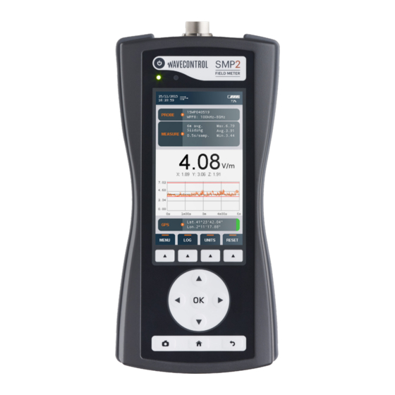
The main screen provides instantaneous and continuous information on the electromagnetic The SMP2 is controlled via the keypad and easy field being measured. access to data is available through the different • Date and time: date and time of the apparatus. - Page 14 Measurement Options. • Logging and average parameters: 1. Average window time. 2. Average type (sliding or tumbling). • The sum of each axis field (for power density 3. Logging time. units): www.wavecontrol.com P. 14...
- Page 15 This information is only displayed when the GPS is switched on. • Lat: latitude. • Lon: longitude. On the right side a colour indicates the quality of the position: • Red: bad. • Orange: average. • Green: good. www.wavecontrol.com P. 15...
-
Page 16: Menu Screen
• MEASUREMENT LOG (allows to see the stored measurements). • GPS (allows to change GPS parameters). • SETTINGS (allows to change general parameters of the unit). • MESSAGES (in case some events are available this menu will appear). www.wavecontrol.com P. 16... - Page 17 • Standard: List of preselected standards. This will affect other parameters that will not be editable. For example: if you choose ICNIRP standard then all the parameters in "MEASUREMENT BEHAVIOUR" section will not be editable as they are defined by the standard. www.wavecontrol.com P. 17...
- Page 18 10 s, 15 s, 30 s, 1 min, 2 min, 5 min, 6 min, 10 min, 15 min and 30 min. • Spatial average: choice between a single temporal log or several spatial measurements that will be represented in a column graphical chart (see 6.1.4). www.wavecontrol.com P. 18...
- Page 19 This image will be available for reporting with the SMP2 Reader software. • Save measurement name: permits to save a name for each measurement. In case it is activated, a pop-up will appear before the measurement starts in order to indicate a name.
-
Page 20: Measurement Log Screen
The arrows are used to select measurement, or “DELETE ALL” to erase all the the next page or the preceding page. memorised data (this is the same as “erase all measurements” on the measurement configuration screen). www.wavecontrol.com P. 20... - Page 21 Where a screenshots taken during the measurement press screenshot exists, you can display that image by on "LIST IMAGES" to enter the SCREENSHOTS pressing OK on the selected sample. LOG screen. www.wavecontrol.com P. 21...
- Page 22 User’s Manual Electromagnetic Field Meter www.wavecontrol.com P. 22...
-
Page 23: Gps Screen
You can choose parameter. between: • Degrees minutes seconds: example: 40° 26′ 46″ N 79° 58′ 56″ W. • Degrees decimal minutes: example: 40° 26.7671′ N 79° 58.9331′ W. • Decimal degrees: example: +40.446 -79.982°. www.wavecontrol.com P. 23... -
Page 24: Settings Screen
5.7 SETTINGS screen This screen has the same layout and behavior as the MEASUREMENT OPTIONS screen. It allows to modify the general parameters of the SMP2. The following parameters can be configured: ALARM allows to activate or deactivate the alarm. When activated, you can define the alarm threshold and units for electric and magnetic field (the ... - Page 25 (Activity may be communicating with PC, keyboard pressing key). When log is activated, automatic turn off is disabled. • System info: indicates the version of the SMP2 software. By clicking on OK, you will have more information about the unit like disk space available.
-
Page 26: Functions
User’s Manual Electromagnetic Field Meter 6. Functions This section describes the main functions of the SMP2, in addition to instantaneous measurement of the electromagnetic field. 6.1 Measurement modes There are several working modes, depending on the probe being used. All probes have the time mode (6.1.1) with spatial average (6.1.4), but only... -
Page 27: Time Domain Measurement
2 samples per second to calculate the average. Measurements are stored in an SQL database. The memory of the SMP2 allows storage of up to 1,000 measurements and 1,000,000 samples. www.wavecontrol.com P. 27... - Page 28 RMS value is also requested. If no limit is selected, the main value displayed by default is the RMS value, and the secondary value is the peak value. www.wavecontrol.com P. 28...
-
Page 29: Fft Mode - Frequency Domain Measurements
FFT graph (span dependent) Each frequency measurement (FFT) contains 400 In frequency mode the parameters of the points. The capacity of the SMP2 allows storage “MEASUREMENT OPTIONS” menu have no of over 1,000 frequency measurements. effect. All parameters have to be chosen from the... - Page 30 40 kHz, change the SPAN to 40 kHz. If no field is detected above 4 kHz, change the SPAN to 4 kHz. Finally, if no field is detected above 400 Hz, change the SPAN to www.wavecontrol.com P. 30...
-
Page 31: Single Frequency Time Mode
MEASUREMENT OPTIONS Spatial average. a) In the FFT mode, place the cursor on the This mode can be used along with the Time desired frequency (you may need to change the mode and the Frequency Log mode. www.wavecontrol.com P. 31... -
Page 32: Time Domain Weighting
6.4 GPS continue with a new position, repeat the previous position or end the measurements. The SMP2 has a built-in state-of-the-art GPS that allows it to display and memorize the position The number of positions measured and the of the device when taking measurements. The... -
Page 33: Battery Information
• Plug the charger into an electrical outlet (110- screen 240 V AC). • Connect the charger to the SMP2. The red LED Li-ion batteries have no “memory effect” and will light up. If it does not light up, the charger is so there is no need to let the battery run down not properly connected. -
Page 34: Smp2 Reader Software
(exclusive service for registered customers, see the SMP2 and Windows will install the drivers chapter 9 and appendix 7). automatically. Before connecting the SMP2 to your PC, run the The following images show the full process: Setup file. Figure 11: Installation of the program www.wavecontrol.com... -
Page 35: Www.wavecontrol.com P
• RAM: 2 GB. 8.3 Using the software When running the software and connecting the SMP2 for the first time, a pop-up window will open to allow you to register to the Wavecontrol intranet. This is required for free software and firmware updates (see chapter 9 for updates and appendix 7 for the intranet). -
Page 36: Measurements Screen
You can use this to find maximum values, Measurements are loaded automatically when ordering samples by value, by clicking on the Field the SMP2 is connected by USB. A list will appear heading. on the left with the measurements stored in the SMP2. -
Page 37: Screenshots Screen
“Click here for measurements” to download the to export screenshots, to create a graph or to data from the SMP2 and display it on the screen. paste a position map using the GPS coordinates. www.wavecontrol.com... - Page 38 User’s Manual Electromagnetic Field Meter Figure 14: SMP2 Export parameters In the exported report, the “Report” tab of the page format report shows the main data of the measure, the associated graph, the GPS position with a map, and the final screenshot (if any), depending on the configuration (see figures 14 and 15).
-
Page 39: Control Centre Screen
Control Centre for managing MonitEM and “Send to Control Centre”. SMP2 devices, you can upload your SMP2 measurements directly to the Control Centre. A new window will open with a new tab “Control Centre”... -
Page 40: Live Measurements
Note: With the Control button pressed, you can also use the arrows on the keyboard to move the cursor on the graph in the same way as the arrows of the SMP2 keypad. When the GPS is switched on with a fixed position, a map will show the position of the SMP2 (this requires an Internet connection). -
Page 41: Software And Firmware Updates
1. Update SMP2 Reader (please follow the instruction in 9.1). Step 1: Registration 2. Run the SMP2 Reader software 3. Connect the SMP2 to the PC using the USB You can register with the intranet in one of these cable. two ways: The SMP2 Reader will automatically detect •... - Page 42 Note 1: Depending on the type of update the process may take from 10 to 30 minutes. Note 2: In case the SMP2 cannot be connected to the mains, please be sure there is enough battery. Note 3: It is recommended to update the firmware without any field probe connected to the SMP2.
-
Page 43: Maintenance
To recalibrate your equipment, please contact your local distributor or Wavecontrol at service@wavecontrol.com. 10.2 Handling the device The SMP2 and its field probes are not watertight. Wavecontrol offers ISO 17025 accredited When using them outdoors, protect them from calibrations at its LabCal Wavecontrol laboratory. -
Page 44: Technical Specifications
100 x 215 x 40 mm (3.94 x 8.46 x 1.57 in) Weight (without probe) 630 g (1.39 lb) including the internal GPS receiver Hardcase, battery charger, USB-mini USB cable, Accessories SMP2 Reader software, user manual, probe calibration certificate www.wavecontrol.com P. 44... -
Page 45: Appendix 1. Available Probes
User’s Manual Electromagnetic Field Meter Appendix 1. Available probes The SMP2 has a wide range of probes that make it adaptable to every sector and application. They include probes for the electric field, magnetic field, electric and magnetic fields, low or high frequencies, high sensitivity or high power, broadband or selective. -
Page 46: Appendix 2. Applications
The wide range of probes that can be used with the SMP2 make a unique system that can easily and accurately measure low and high frequency fields as well as static fields. - Page 47 User’s Manual Electromagnetic Field Meter Application Type of field Frequency range Standard SMP2 + probe configuration Broadcast Electric and Tens to hundreds of IEC 62577 • Broadband measurement. magnetic fields. MHz. EN 50420 • Spatial average. EN 50421 • Probes: WPF3, WPF6, WPF8, WPH60...
- Page 48 IEEE Std C95.3 600 kHz, 13 MHz, 27 IEEE Std C95.3.1 IEEE Std C95.6 Railway Magnetic fields. DC - 20 kHz EN 50500 • Broadband measurement and weighted measurement. IEEE Std C95.3.1 • Probes: WPH-DC, WP400 IEEE Std C95.6 www.wavecontrol.com P. 48...
-
Page 49: Appendix 3. Static Field Measurements: Wph-Dc
If it is found that the field is close to 30 mT, where the SMP2 will be placed to take the final measurement, precautions should be taken to prevent the SMP2 from moving, or using the extension cable as mentioned previously. - Page 50 • Position the tip of the probe in the Zero Gauss variable or both). chamber. • Press the "Zero" button in the SMP2 menu. • Repeat these last 2 operations each time you want to compensate for any change in temperature.
-
Page 51: Appendix 4. Weighted Peak Method
Electromagnetic Field Meter Appendix 4. Weighted Peak Method Introduction The SMP2 + WP400 or WP400-3 field probe The choice of option will depend upon the specific combination is the most complete and compact application and the objective of the measurement available on the market for evaluation of human or evaluation. - Page 52 User’s Manual Electromagnetic Field Meter Measurement methods The SMP2 + any of the selective field probe The “MEASUREMENT OPTIONS” menu is used to (WP400, WP400-3 or WPH-DC) combination select the measurement time, the log interval, the allows you to choose any of 3 measurement average interval and the average type, as shown methods.
- Page 53 Once the measurement behavior is defined, the To start the measurement, now all that you need next step is to choose the “Time” option on the to do is select “LOG” on the dynamic menu: “MODE” dynamic menu: www.wavecontrol.com P. 53...
- Page 54 User’s Manual Electromagnetic Field Meter 2. Selective measurement (FFT): The spectrum then appears on the SMP2 display. The SMP2 + WP400 (or WP400-3 or WPH-DC) You may now select the desired span: allows you to make selective measurements by means of real-time FFT-based signal analysis using digital signal processing techniques.
- Page 55 (each second). This tracking can be done in two ways: • In FFT mode place the cursor on the desired frequency and change to “Freq. log” on the “MODE” menu: www.wavecontrol.com P. 55...
- Page 56 (selectable). This gives a result directly as a percentage (%) of the limits for which we are measuring exposure. The SMP2 offers an extensive list of limits corresponding to the different standards or laws of different countries. You can use WPM for any existing limits.
- Page 57 User’s Manual Electromagnetic Field Meter The figure below shows the weighted result for the broadband electric field in respect of the “Low AL” limits of Directive 2013/35/EU. www.wavecontrol.com P. 57...
- Page 58 1 k Samples/s for SPAN 400 Hz 10 Square- Digital Average Sensor Square root Filter Digital Square- Sensor Square Average Filter root Square- Digital Average Sensor Square root Filter Square- root Value Peak Peak Square- Detector root Value www.wavecontrol.com P. 58...
- Page 59 This function could be useful, for fundamental overloading the dynamic range. example, to measure pulses generated by welding equipment. www.wavecontrol.com P. 59...
- Page 60 User’s Manual Electromagnetic Field Meter Response with the different filters, slightly different if a limit has been selected or not. Figure 19: Filter response when a limit is applied Figure 20: Filter response when no limit is applied www.wavecontrol.com P. 60...
-
Page 61: Appendix 5. Radar Measurements
MODE: select the sampling mode for the probe Note 2: Max fast RMS does not allow averaging, since the value obtained every 0.5 sec is the maximum value. www.wavecontrol.com P. 61... -
Page 62: Appendix 6. Communication Protocol
Ports USB: it emulates a serial port service with CDC, The XML format accepted by the SMP2 parser is automatically negotiated rate, 8 bits, no parity,1 as follows : bit stop. The Vendor ID and Product 0x1FC9 ID 0x807B of the USB may be used to find the port number opened by the driver. - Page 63 “ " & & ‘ ' < < The XML format used by SMP2 is as follows: Response: General format of the correct reply PC SMP2 <?xml version=”1.0” encoding=”ISO-8859-1”?> <reply> <result> <instruction>[String that identifies the command]</instruction> [Specific results of the command] </result>...
- Page 64 YYYY-MM-DD YYYY-MM-DD HH:mm:ss HH:mm:ss set time INFO_SYSTEM device: identify device SMP2 get info about device serial_micro: unique ID of micro crontoler firmware_version: firmware version serial_device: device serial number hardware_version: hardware version MEASURE_START...
- Page 65 User’s Manual Electromagnetic Field Meter Units Below it is described in c# the units of SMP2 with the identification number that the command GET_SAMPLE returns. enum E_FieldUnits E_FIELD_V_m = 0, // E - V/m E_FIELD_kV_m = 1, // E - kV/m...
- Page 66 User’s Manual Electromagnetic Field Meter Example of Commands These examples have been automatically generated by the software SMP2 and should be sent unformatted (ie no spaces and line breaks between tags). System info <?xml version=”1.0” encoding=”ISO-8859-1”?> <cmd><instruction>INFO_SYSTEM</ md5>c1c0060ec77a5b477c8e164012df8e4f </md5></cmd> SMP2 time <?xml version=”1.0”...
- Page 67 (string_parts.Length == 2) //Calculate MD5 of the chunk before “</cmd> using (var md5 = MD5.Create()) string md5_str = BitConverter.ToString(md5. ComputeHash(Encoding.UTF8.GetBytes(string_parts[0]))).Replace(“-”, “”).ToLower(); //Add it to the result result = string_parts[0] + “<md5>” + md5_str + “</md5></ cmd>”; return result; www.wavecontrol.com P. 67...
-
Page 68: Appendix 7. Wavecontrol Intranet
One of the important things that you can do via the intranet is keep your SMP2 device always up to date. Wavecontrol offers you regular updates of the SMP2 firmware and the SMP2 Reader software, free of charge. -
Page 69: Declaration Of Conformity (Doc)
C/ Pallars, 65-71 08018 Barcelona (Spain) Object of the declaration: SMP2 Electromagnetic Field Meter The above mentioned product complies with the essential requirements, which are specified in the 2004/108/EC Directive on the approximation of the laws of the Member States relating to electromagnetic compatibility. - Page 70 +34 93 320 80 55 www.wavecontrol.com info@wavecontrol.com Safety, Quality, Service...
Need help?
Do you have a question about the SMP2 and is the answer not in the manual?
Questions and answers