Table of Contents
Advertisement
Quick Links
Download this manual
See also:
User Manual
Advertisement
Table of Contents

Related Manuals for WAVECONTROL SMP2


Summary of Contents for WAVECONTROL SMP2
- Page 1 SMP2 Portable Electromagnetic Field Monitoring System User’s Manual V1.11 WAVECONTROL C/ Pallars 65-71 · 08018 Barcelona (SPAIN) Tel. (+34) 933 208 055 Fax. (+34) 933 208 056 www.wavecontrol.com...
-
Page 2: Table Of Contents
4.2.2 Screw connector..................................8 4.2.3 Push-pull connector................................9 4.3 External connections......................4.3.1 USB.......................................9 4.3.2 Fibre optic...................................10 5 SMP2 – INITIAL USE........................... 5.1 Switching the apparatus on and off.................10 5.2 Main screen........................5.3 Menu screen........................5.4 Measurement configuration screen.................13 5.5 Measurement log screen....................14 5.6 GPS screen........................ -
Page 3: Warnings And Precautions
Wavecontrol SMP2. Congratulations for your acquisition of a This manual provides you with instructions for using and handling your SMP2. Please read this Manual carefully before using your SMP2. WARNINGS AND PRECAUTIONS Review this manual and become familiar with all the instructions for using and handling your SMP2. -
Page 4: Introduction
INTRODUCTION SMP2 Portable Electromagnetic Field Monitoring System can measure electromagnetic field levels generated by any source within the frequency range of the probe attached to the system. It combines 2 instruments in 1: Broadband measurements and selective measurements (FFT), including % direct EMF exposure assessments to limit lines by using the weighted peak exposure (WPE) technique. -
Page 5: First Steps
4. USB key containing the User’s Manual and SMP2 software 5. USB – mini USB cable 6. Fibre optic link (optional) If any of those components is missing, please contact Wavecontrol. Optional fibre optic link below SMP2 and USB cable... -
Page 6: Getting Started
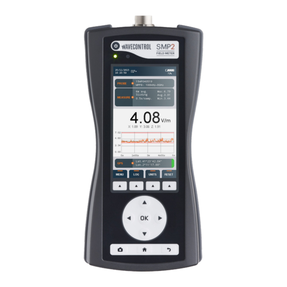
GETTING STARTED Overview SMP2 The front panel of the contains the user interface, made up of the screen and keypad. Figure 2: Front The keyboard presents 8 standard buttons, 4 virtual buttons (below the screen) and 1 ON/OFF button. ... - Page 7 SMP2 The top of the holds the field probe connector. Probe connector Hidden On/off antenna button Status Light sensor Figure 3: Top Probe connector: (see 4.2) On / Off button: switches the equipment on and off. Status LED: when the unit is off, red means charging, green charged. When the unit is on, green LED should be always on.
-
Page 8: Field Probes
SMP2 is a highly versatile EMF measurement device that requires connection of the proper field probe to obtain the best results for each application. Only Wavecontrol field probes will work with the device. If the device is switched on with no field probe attached, it will not show any field value and therefore no measurement will be saved to memory. -
Page 9: Push-Pull Connector
A USB to mini USB cable is delivered with the SMP2. After installing the SMP2 software (First install the software see 8.1) just plug the cable to the SMP2 and to the computer. You will be able to download stored measurements to the computer or update the SMP2 firmware. -
Page 10: Fibre Optic
PC without interfering with the measurements. To connect the fibre optic link: plug the fibre to the SMP2 (respect the colour • Breakable part code, grey side is looking up) - Page 11 Battery fully charged Probe information: serial number of the field probe attached to the apparatus and its frequency information. Icons Battery Date and time Probe information Measurement information Field information Graph GPS information Functions Figure 10: Main screen Measurement information: •...
-
Page 12: Menu Screen
Field unit: unit of measurement of the field value shown on the display. This unit • applies to the total field, the field on each axis and the maximum, minimum and average values. Field on each axis: the field measured on each axis for isotropic three-axis probes. •... -
Page 13: Measurement Configuration Screen
Measurement configuration screen This screen is used to configure different parameters related to measurement behaviour. It appears as a menu with a scrolling bar. The parameters to be configured are shown on the left different options each parameter shown right. The keypad is used to move along the menu. -
Page 14: Measurement Log Screen
Settings screen This screen has the same layout and behavior as the measurement configuration screen. It allows to modify the general parameters of the SMP2. The following parameters can be configured: Alarm: allows to activate or deactivate the alarm. When activated, you can define the ... -
Page 15: Functions
(Activity may be communication with PC, keyboard pressing key). When log is activated, automatic turn off is disabled. System info: indicates the version of the SMP2 software. By clicking on OK, you will have more information about the unit like disk space available. FUNCTIONS This section describes the main functions of the SMP2, in addition to instantaneous measurement of the electromagnetic field. -
Page 16: Low Frequency Time Domain Measurement With Wp50 Or Wp400
(FFT) for the selected SPAN and the total field value representing the RMS value. (Span has no effect on the total field value) Measurements in frequency domain contain frequency information of the measured field. One SMP2 measurement contains 401 frequency points so the memory of the allows storage of up to 1000 frequency measurement. -
Page 17: Scenarios
If you are not sure if there is field below 10 Hz, then put the filter to 1 Hz. In this case always measure with the SMP2 on a tripod and the fibre link in order to avoid any external perturbation. -
Page 18: Time Domain Weighting
The alarm will only sound if the alarm function has been activated and if the sound is enabled in the Settings screen. SMP2 is available with a built-in latest-generation GPS ublox engine 7 allowing you to display and memorise the position of the device when taking measurements. -
Page 19: Battery Information
Li-ion battery charge controller so you can leave the apparatus charging for more than the specified 5 hours with no danger of damaging the battery. Note: it is recommended to do a complete charge from time to time for SMP2 to recalibrate the battery capacity. -
Page 20: Software
During the process the setup file will install the software and all the necessary drivers. Images below show the complete process: Figures 11: Installation of the software When the installation is finished you can connect the SMP2, windows will install the driver automatically. - 20 -... -
Page 21: System Requirements
System requirements Operating system: Minimum Windows 7 RAM: 2 GB Using the PC software The SMP2 software presents several features: downloading stored measurements • displaying measurements in graph and table format • displaying stored screenshots • exporting measurements and screenshots to excel files •... -
Page 22: Screenshots Screen
8.3.2 Screenshots screen This tab allows to download and display screenshots made with the SMP2. Click one line to be able to see the screenshot. Each line contains a selection box to select it, a date of creation and a sample reference. This last parameter represents the internal database identification of the sample. -
Page 23: Control Centre Screen
Depending on Setting, these files can contain also a graph of the measurement and all the screenshots made during the measurement. Figures 14 shows an example of the 2 worksheets. SMP2 Figure 14: export examples Note 1: Graph generation can be very time consuming, so it is not recommended if the measurement contains lots of samples. -
Page 24: Live Screen
Live screen This screen is only available with the fibre optic link (see 4.3.2). It provides a real time display of the data being measured by the SMP2. You will see the instant total field value along with each axis value. -
Page 25: Maintenance
This section explains the maintenance of the apparatus that can be carried out by the user. If you have any questions about how to maintain the SMP2, please consult Wavecontrol. Maintenance by the user is limited to the outside of the apparatus and its connections. Any... -
Page 26: Technical Specifications
-10 ºC a +50 ºC Size (without field probe) 100 x 215 x 40 mm Weight (without probe) 610 g (including the internal GPS receiver) Hardcase, battery charger, USB-mini USB cable, Accessories SMP2 Reader software, user manual, probe calibration certificate - 26 -... -
Page 27: Warranty
If any such product proves defective during this warranty period, Wavecontrol, at its discretion, will either repair the defective product without charge for parts and labour, or provide a replacement in exchange for the defective product. -
Page 28: Annex 1: Wp400 Probe Special Functions
Auto-increasing: range will only increase. This is important when measuring sporadic • peaks because even when field is low, SMP2 will be ready for the next peak to be measured. This option should be used when single peaks occur at more than 1 second separation. - Page 29 WP400 High Pass Filter (HPF) response when no Limit is applied HPF 100hz (dB) HPF 25hz (dB) HPF 10hz (dB) HPF 1Hz (dB) -3dB 1000 Figure 18: Filter response when no limit is applied (For limit see 6.3) - 29 -...
-
Page 30: Annex 2: Communication Protocol
ID 0x6001 to find the number of communication port opened by the FTDI driver. Format of commands and responses Communication is through the exchange of string with the XML format. The SMP2 checks the frames received and if not well formed it is rejected. - Page 31 The XML format used by SMP2 is as follows: Response: General format of the correct reply SMP2 → PC <?xml version="1.0" encoding="ISO-8859-1"?> <reply> <result> <instruction>[String that identifies the command]</instruction> [Specific results of the command] </result> <md5> [MD5 of the string from “<?xml” to the previous character of the “<md5>”, tag in ASCII hex] </md5>...
- Page 32 YYYY-MM-DD format YYYY-MM-DD HH:mm:ss set time HH:mm:ss INFO_SYSTEM device:identify device SMP2 get info about device serial_micro: unique ID of micro crontoler firmware_version: firmware version serial_device: device serial number hardware_version: hardware version MEASURE_START start measurement...
- Page 33 Units Below it is described in c# the units of SMP2 with the identification number that the command GET_SAMPLE returns enum E_FieldUnits E_FIELD_V_m = 0, // E - V/m E_FIELD_kV_m = 1, // E - kV/m E_FIELD_uW_cm2 = 2, // E - uW/cm2...
- Page 34 Limitations and Timeout The XML commands from the PC to the SMP2 can be up to 32768 bytes. The SMP2 expects to receive complete commands in less than 3 seconds (counting from the time of receipt of the first byte); If after this time it does not have a full and valid response, an error message is sent and discards the information received so far.
- Page 35 Example c# code to generate the MD5 using System; using System.text; using System.Security.Cryptography; private string AddMd5(string cmd) String formatted_xml = cmd; String result = string.Empty; string[] string_parts; /* Add a <md5>MD5_VALUE</md5> tag before the closing </cmd> tag. */ (!formatted_xml.Contains("<md5>")) /* Split result: before "</cmd>" and after "</cmd>": */ string[] tokenizer = string[1];...
- Page 36 DECLARATION OF CONFORMITY (DoC) Manufacturer: Wavecontrol, S.L. C/ Pallars, 65-71 08018 Barcelona (Spain) Object of the declaration: SMP2 The above mentioned product complies with the essential requirements, which are specified in the directive 2004/108/EC on the approximation of the laws of the Member States relating to electromagnetic compatibility.
Need help?
Do you have a question about the SMP2 and is the answer not in the manual?
Questions and answers