
Related Manuals for WAVECONTROL SMP


Summary of Contents for WAVECONTROL SMP
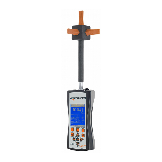
- Page 1 Portable Electromagnetic Field Monitoring System User’s Manual V3.9.8 WAVECONTROL C/ Pallars 65-71 · 08018 Barcelona (SPAIN) Tel. (+34) 933 208 055 Fax. (+34) 933 208 056 www.wavecontrol.com...
-
Page 2: Table Of Contents
5.6.3 IS measurement......................16 5.6.4 Maximum and minimum field..................16 5.6.5 Alarm..........................16 5.6.6 GPS..........................17 6 RECHARGING THE BATTERY................18 7 COMMUNICATION SMP - PC ................19 7.1 I ....................19 NSTALLING THE HARDWARE 7.1.1 USB driver installation ....................19 7.2 D .....................20 ATA DOWNLOAD SOFTWARE 7.2.1 CSV exportation......................21... -
Page 3: Warnings And Precautions
Adjustment, maintenance, or repair of the equipment must be performed only by qualified personnel. Please contact Wavecontrol. Never overtighten when screwing the SMP on the tripod since the thread engagement could break down Environmental information... -
Page 4: Introduction
INTRODUCTION Portable Electromagnetic Field Monitoring System can measure electromagnetic field levels generated by any source within the frequency range of the probe attached to the system. For example it can measure fields generated by different sources such as mobile telephone base stations, radio and television transmitters and repeaters, DECT systems, Wi-Fi systems, etc. -
Page 5: First Steps
2. Electromagnetic field probe 3. Battery charger 4. CD or USB key containing the User’s Manual and data download software 5. USB – mini USB cable If any of those components is missing, contact Wavecontrol. Field Probe and USB cable below... -
Page 6: Getting Started
GETTING STARTED Overview The front panel of the contains the user interface, made up of the screen and keypad Figure 1: Front Menu: Opens the configuration menu. • : Arrows allow you to move through the menu options and the data stored in •... - Page 7 Log/RD: Stores measurements in the memory and deletes memory registers. • The top of the holds the field probe connector, the GPS antenna and the On /Off switch. On/Off switch antenna Probe connector Figure 2: Top Probe Connector: The probe connector is a push-pull connector. •...
-
Page 8: Connecting The Field Probe
The only reads data measured by Wavecontrol field probes. If there is no field probe connected to the device when it is switched on, it will not provide any field values and therefore no measurements can be stored in the memory. -
Page 9: Disconnecting The Probe
4.2.2 Disconnecting the probe You do not need to switch the device off before you disconnect the field probe. Pull the connector of the probe firmly with one hand (pulling with the thumb) while you hold the with your other hand as shown in the pictures below: Figure 5: Disconnecting the probe Important: Pull the connector. -
Page 10: Operation
OPERATION is designed for simple and intuitive operation with 2 basic functions: instant and averaged field measurement storage of field measurements in memory Several additional functions make the a very complete field measurement system. is controlled via the keypad and easy access to data is available through the different screens. - Page 11 Probe: XXXXXXX Alarm: 2500 999.99 Total field mW / cm Field unit Electric field Field on 673.98 45.78 each axis 25.54 Maximum and : 99.78 : 24.54 minimum value Average : 99.78 value [Arith. – 10 min] Type of average Lat: 47º58’02,54”...
-
Page 12: Configuration Screen
Lat: Latitude Lon: Longitude Height: Altitude Date and time: Date and time of the apparatus. • Batt: Battery charge level. • Battery discharged Battery fully charged The keypad for this screen has the following functions: Menu: Access to the configuration screen. Memory: Access to the memory screen. - Page 13 Avg. type: Three types of average are available: arithmetic, sliding and IS. See sections • 5.6.2 and 5.6.3 below for more information on this function. Avg. interval: Used to select the time interval for calculation of the average (see section •...
-
Page 14: Memory Screen
Memory screen The memory screen is used to display the distribution of data stored in the different registers. The screen provides a list of registers with the following information for each register: • ID: Register identification number. • Name: Register name. •... -
Page 15: Functions
Functions This section describes the main functions of the , in addition to instantaneous measurement of the electromagnetic field. 5.6.1 Memorisation of measurements One of the main functions of the is storage of measurements in memory for later study or processing. The memory of the allows storage of up to 62,400 points of memory without positioning information, and up to 27,300 points when storing the GPS data. -
Page 16: Is Measurement
samples the field twice per second and so for an average interval of 10s, for example, the will calculate the average each 10s of the 20 samples taken twice per second. Sliding average : The arithmetic average of a window of ‘average_interval x 2’ samples that is moved twice each second. -
Page 17: Gps
5.6.6 is available with a built-in latest-generation GPS SiRFstarIII receiver, allowing you to display and memorise the position of the device when taking measurements. The incorporation of SiRFstarIII functions makes the receiver extremely sensitive and precise, allowing exact positioning even in built-up areas with poor satellite visibility. The GPS is enabled/disabled through the configuration menu as explained in section 5.3. -
Page 18: Recharging The Battery
The battery will function normally at temperatures ranging from -20ºC to +45ºC. However, we recommend avoiding low temperatures to prevent its useful life from being shortened. Only the battery charger supplied by Wavecontrol should be used to recharge the battery of * GPS disabled... -
Page 19: Communication Smp - Pc
COM port list as ‘USB Serial Port’ (Start / Control panel / System / Hardware / Device manager / Ports (COM & LTP)) Once the driver is installed, you can download data from the at any time. If you have any problems during the driver installation process, contact Wavecontrol. -
Page 20: Data Download Software
Note: If the operating system is Windows XP,the Microsoft.Net Framework must be installed on the PC. If SMP Reader does not work after installation, install the executable file that appears in the “NET Framework2/NET32” folder of the CD if your PC is 32 bits, or the executable file from “NET Framework2/NET64”... -
Page 21: Csv Exportation
(Type), the probe used to take the measurement (Probe) and lastly, whether or not the measurements contain GPS positioning data. If the software is unable to communicate with the SMP, check the connection between the PC and the SMP. Ensure that the ‘USB Serial Port’ associated with the figures on the list of COM ports. -
Page 22: Gis Web Site Exportation
If you have been accessed to the GIS web site in SMRF control center, you can download your SMP measurement directly with this software. Note that you can only upload a measurement at a time. To do so please make sure: you have a valid URL, user and password in the Option menu (see fig 9) –... -
Page 23: Real Time Data Visualisation
– better not to send too large picture) Figure 11: SMP reader GIS upload information When you have filled all values, click on send. When OK appears, you can close this window. This measurement will appear automatically in the web site. - Page 24 To activate this function, you will have to send this command to the unit: USB_ON (with <CR><LF> at the end). To deactivate this mode the command is USB_OFF.
-
Page 25: Firmware Updating
The software used for the update is Fujitsu Flash MCU Programmer. It can be installed from the installation CD ('Fujitsu Flash Programmer' folder). This function should only be used when recommended by Wavecontrol and under our supervision to avoid any malfunction of the apparatus caused by improper updating of the firmware. - Page 26 If the number of the assigned COM port is higher than 8, change it to a port number between 2 and 8. Start Fujitsu Flash MCU Programmer. Set the COM port by clicking on Set Environment and selecting the port number.
- Page 27 Target Microcontroller: MB90F583B/C/CA Crystal Frequency: 16 MHz Select the file (Hex File) with the firmware update. Wavecontrol will provide you with this file. Click on Open and find the file, which have the extension ‘.mhx’. Start the update by clicking on the Full Operation(D+E+B+P) button.
-
Page 28: Maintenance
The apparatus and the probes should also be protected from any strong blows or vibrations. Regular recalibration does not require recalibration. Wavecontrol recommends that the field probe/s used with the should be recalibrated every 2 years. Wavecontrol can recalibrate the probe/s for you. Contact Wavecontrol for information on the cost and scheduling of recalibration. -
Page 29: 10 Technical Specifications
-10 ºC a +45 ºC Size (without field probe) 100 x 215 x 40 mm Weight (without probe) 490 g (including the internal GPS receiver) Hardcase, battery charger, USB-mini USB cable, SMP Reader software, user Accessories manual, probe calibration certificate... -
Page 30: 11 Warranty
In order to obtain service under this warranty, the Customer must notify Wavecontrol (or one of its distributors) of the defect before the expiration of the warranty period, by sending a Failure Report... - Page 31 DECLARATION OF CONFORMITY (DoC) Manufacturer: Wavecontrol, S.L. C/ Pallars, 65-71 08018 Barcelona (Spain) Object of the declaration: The above mentioned product complies with the essential requirements, which are specified in the directive 2004/108/EC on the approximation of the laws of the Member States relating to electromagnetic compatibility.
Need help?
Do you have a question about the SMP and is the answer not in the manual?
Questions and answers