Table of Contents
Advertisement
Quick Links
Advertisement
Table of Contents

Related Manuals for Uniden Grant


Summary of Contents for Uniden Grant
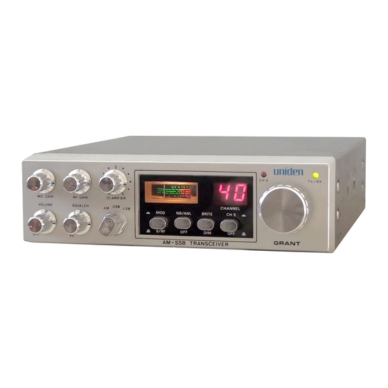
- Page 1 / ^ D Channel AM/SSB л VJHlMIN I Mobile CB Radio OWNERS MANUAL...
- Page 2 INTRODUCTION U N ID E N C O R P O R A T IO N O F A M E R IC A has combined superb workmanship and modem styling with the very latest state-of-art circuitry to bring you the G R A N T Citizens Band Trasnceiver.
-
Page 3: Installation
INSTALLATION M O B IL E STATIO N IN ST A L L A T IO N Plan the location of the transceiver and microphone bracket before starting the installation. Select a location that is convenient for operation and does not interfère with the driver or passenger in the vehicle. - Page 4 POWER CO R D CONNECTION: PO SITIVE G R O U N D SY ST EM If you are operating on a positive ground system, connect the black DC power cord from the transceiver to the negative, or (-), battery terminal or other convenient point, and connect the red power lead to the chassis or vehicle frame, or (+) battery terminal.
-
Page 5: Operating Procedure
OPERATING PROCEDURE TO RECEIVE: The G R A N T opérâtes on 40 A M channels, 40 Upper Side Band channels and 40 Lower Side Band channels. When you receive the S S B signal in the proper mode (USB or LSB), audio sound may be either too high pitched or low pitched, indicating that your receiver may not be tuned to the exact same frequency as the transmitter to which it is listening. -
Page 6: Controls And Their Functions
CONTROLS AND THEIR FUNCTIONS 1. O FF/O N V O L U M E : To turn the transceiver on, rotate this control clockwise past click. To turn the transceiver off, rotate the control counterclockwise past click. Rotate the control clockwise for a comfortable audio level. 2. - Page 7 5. M IC G A IN : This control is used to adjust, as required, microphone input sensitivity for optimum amount of modulation in transmit. U N I D E N C O R P O R A T IO N O F A M E R IC A citizen's band transceivers hâve been designed to permit the user to attain levels of modulation up to 100% depending on the setting of the microphone gain control, using the microphone provided with the unit.
- Page 8 13. C H A N N E L IN D IC A T O R : Light Emitting Diode(LED) indicates the channel number in use. 14. C H A N N E L S E L E C T O R KN O B: This knob selects the desired channel for transmission and réception.
- Page 9 19. E X T E R N A L S P E A K E R JA C K : The External Speaker Jack is used for remote receiver monitoring. The external speaker should hâve 8 ohm impédance and be rated to handle at least 4.0 watts.
-
Page 10: Specifications
SPECIFICATIONS G E N E R A L F.C.C. Type Number 1005002 Channels 40A M , 40LSB, 4 0U SB Frequency Range 26.965 to 27.405 MHz Frequency Control Phase Locked Loop(PLL) synthesized circuitry. Frequency Tolérance 0.005% Frequency Stability 0.001% Operating Température Range -20°C to +50°... - Page 11 A M and SSB: 350 to 2500 Hz. Frequency Response 52 ohms, unbalanced. Output Impédance 7.8 MHz, crystal lattice type S SB Filter 6 dB @2.2 kHz 60 dB @4.6 kHz R E C E IV E R SSB: Less than 0.25 p V for 10 dB Sensitivity (S+N)/N at greater than % watt of radio output.
-
Page 12: Servicing Your Transceiver
SERVICING YOUR TRANSCEIVER The technical information, diagrams and charts will be supplied upon request. It is the user's responsibility to see that this radio is operating at all times in accordance with the F.C.C. Citizens Radio Service régulations. We highly recommend that you consult a qualified radiotéléphone technician for the servicing and alignment of this CB radio product. - Page 13 O PERA TO R T R O U B LE SH O O T IN G Should be unit malfunction or not perform properly, the operator should perform the procedures ii.dicated below: 1. If the transceiver is completely inoperative. * Check the power cord and fuse. 2.
- Page 14 CIRCUIT DIAGRAM FOR GRANT • nt'l’UCI ••U4I *4 » л!«1 c*««ini eut...
- Page 15 BLOCK DIAGRAM FOR GRANT Printed in Taiwan...
- Page 16 T W O -Y E A R LIM ITED WARRANTY W A R R A N T O R . U N I D E N C O R P O R A T I O N O F A M E R I C A ( " U N I D E N " ) E L E M E N T S O F W A R R A N T Y .
- Page 17 CIRCUIT DIAGRAM FOR GRANT MHCC NOUS: ■ RESrSTAMCC VALUES I « n im UM USS OT £R $C ЧОТЕР. ( K l KILO ОНИ И - НЕС ОИЫ J i САЛАС.TANCE VALUES ARE iMOtCATEO IM HiC.RWARACS UM CSS OTERWiSf iP E D F IEO .
Need help?
Do you have a question about the Grant and is the answer not in the manual?
Questions and answers