Advertisement
Available languages
Available languages
Quick Links
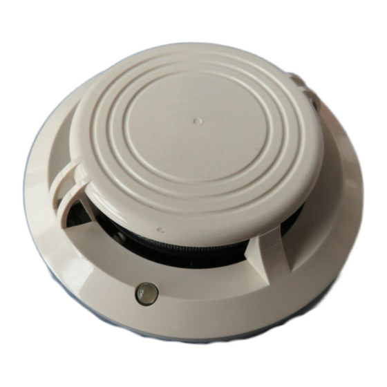
INSTALLATION AND MAINTENANCE INSTRUCTIONS FOR MODEL TC840ME
ANALOGUE ADDRESSABLE MULTI-CRITERIA SMOKE SENSOR
Before installing the sensor, please thoroughly read System Sensor's wiring and installation manual, I56-407-XX, Guide for Proper Use of Smoke
Detectors. This manual includes detailed information on sensor spacing, placement, zoning and special applications. Copies of this manual are
available at no charge from Honeywell.
GENERAL DESCRIPTION
Model TC840ME analogue addressable sensors are microprocessor controlled plug-in type smoke sensors that combine photo electronic and
fixed temperature thermal (58°C) sensing elements with addressable-analogue communications. These sensors are designed for open area
protection and must only be connected to control panels that use a compatible proprietary analogue addressable communication
protocol for monitoring and control.
Two LEDs on each sensor light to provide a local 360° visible sensor indication. The LEDs can be latched on by code command from the control
panel for an alarm indication. They can also be unlatched to the normal condition by code command. Remote LED indicator capability is
available as an optional accessory wired to the standard base terminals.
SPECIFICATIONS
Operating Voltage Range:
15 to 32 VDC
Max. Standby Current:
250 µA @ 24 VDC (no communication)
Max. Avg. Standby Current:
300 µA (one communication every 5 sec. with LED blink enabled)
Max. Alarm Current (LED on):
7 mA @ 24 VDC
Operating Humidity Range:
10% to 93% Relative Humidity, non-condensing
Temperature Range:
-30°C to 80°C
Nominal Activation Temperature:
58°C
Height:
43 mm installed in B501 Base
Diameter:
102 mm installed in B501 Base
Weight:
111 g
This detector has been independently tested and certified to EN54: 2000 parts 5 and 7 and CEA4021.
WIRING GUIDE
Refer to the installation instructions supplied with the plug-in sensor bases for wiring details. All bases are provided with terminals for power and
an optional Remote Indicator.
NOTE: All wiring must conform to applicable local and national codes and regulations.
NOTE: Verify that all sensor bases are installed and that polarity of the wiring is correct at each base.
Disconnect loop power before installing sensors
SENSOR INSTALLATION
1.
Set the sensor address (see Figure 1) by using a flat blade screwdriver to turn the two rotary switches, selecting the desired number
between 01 and 99. Record the address on the label attached to the base.
2.
Insert the sensor into the base and rotate it clockwise with gentle pressure until it drops into place.
3.
Continue to rotate the sensor until it locks into the base.
4.
After all the sensors have been installed, apply power to the system.
5.
Test the sensor as described under TESTING.
6
Reset the sensor by communication command from the panel.
Tamper Resistance
Model TC840ME includes a feature that, when activated, prevents removal of the sensor without the use of a tool. Refer to the installation
instructions for the sensor base for details of how to use this feature.
Dust covers help to protect units during shipping and when first installed. They are not intended to provide complete protection
against contamination therefore sensors should be removed before construction, major re-decoration or other dust producing work
6 7
8
7
8
9
6
9
5
5
4
4
3
3
2
2
1
1
0
0
TENS
ONES
H600-06-00
WARNING
CAUTION
Figure 1: Rotary Decade address Switch
is started. Dust covers must be removed before system can be made
operational.
TESTING
Sensors must be tested after installation and following periodic maintenance.
However, before testing, notify the proper authorities that the smoke detector system
is undergoing maintenance and the system will be temporarily out of service. Disable
the zone or system undergoing maintenance to prevent unwanted alarms.
In addition, check to ensure that the LEDs blink (if this feature is operational under
software command). If they do not, power has been lost to the sensor (check the
wiring).
Test the sensors as follows:
Magnet Test
1.
Test the sensor by positioning the test magnet (Model M02-24, optional) against
the sensor body approximately 2cm from the LED as indicated in Figure 2.
2.
Both LEDs should latch on within 30 seconds indicating an alarm and activating
the panel.
Smoke Test
1.
Use either a canned smoke aerosol or a detector tester for generating artificial
smoke to test the detector. Inject the smoke into the detector's chamber using
the test smoke as recommended by the manufacturer and ensure that it is
present until an alarm occurs on the detector.
2.
The red alarm LED should latch on within 30 seconds indicating an alarm and
activating the panel into a condition to indicate the detector under test.
Direct Heat Method (Hair dryer of 1000-1500 watts).
1.
Direct the heat toward the sensor from its side. Hold the heat source about 15
cm away to prevent damage to the cover during testing.
2.
The LEDs on the sensor should light when the temperature at the detector
reaches 58°C. If the LEDs fail to light, check the power to the sensor and the
wiring in the sensor base.
3.
Reset the sensor at the system control panel.
If the sensor fails these tests, they should be returned for repair.
MAINTENANCE
Before cleaning, notify the proper authorities that the system is undergoing
maintenance and will be temporarily out of service. Disable the system to prevent
unwanted alarms.
1.
Remove the sensor to be cleaned from the system.
2.
Remove the sensor cover. Use a small flat blade screwdriver to gently release
each of the four cover removal tabs that hold the cover place. Use caution to
avoid damaging the thermistors (see Figure 3).
3.
Vacuum the outside of the screen carefully without removing it.
4.
Remove the sensor screen. Pull the screen straight away from the sensing
chamber until it snaps out of place. Replacement screens are available.
5.
Remove the chamber cover by pulling it gently away from the sensing chamber
until it snaps out of place, being careful not to damage the thermistors.
6.
Use a vacuum cleaner and/or clean, compressed air to remove dust and debris
from the sensing chamber and sensing chamber cover.
7.
Re-install the sensing chamber cover by aligning the arrow moulded on the
cover with the arrow printed on the circuit board and sliding the cover over the
chamber, gently pressing it home until it snaps into place.
8.
Re-install or replace the sensing chamber screen by sliding it over the sensing
chamber. Rotate the screen until the locating tabs on the bottom rim locate in
the cutouts in the chamber base, and the top of the screen is flush with the top of
the chamber.
9.
Re-install the sensor cover. Use the cover removal tabs, LEDs and thermistors
to align the cover with the sensor. Snap the cover into place.
10.
When all sensors have been cleaned and re-installed, restore power to the loop
and test the sensor(s) as described under TESTING.
After completion of maintenance and testing, notify the proper authorities that the
system is operational.
LIMITATIONS OF SMOKE DETECTORS
The TC840ME Multi Criteria detector is designed to activate and initiate emergency action, but will do so only when used in conjunction with other
equipment. Fire detectors will not work without power.
TC840ME detectors will not sense fires which start where smoke or heat does not reach the detectors. Smoke or heat from fires in
chimneys, in walls, on roofs, or on the other side of closed doors may not reach the detector and trigger the unit.
A detector may not detect a fire developing on another level of a building. Hence, detectors should be located on every level for a building.
Fire detectors also have sensing limitations. In general, detectors cannot be expected to provide warnings for fires resulting from inadequate
fire protection practices, violent explosions, escaping gas, improper storage of flammable liquids like cleaning solvents, other safety hazards, or
arson. Fire detectors used in high air velocity conditions may fail to alarm due to dilution of smoke densities created by such frequent and rapid
air exchanges. Additionally, high air velocity environments may create increased dust contamination, demanding more frequent maintenance.
Fire detectors contain electronic parts, and cannot last forever. Even though detectors are made to last over 10 years, any of these parts
could fail at any time. Therefore, test your fire detection system at least semi-annually. Clean and take care of your fire detectors regularly. Taking
care of the fire detection system you have installed will significantly reduce your product liability risks.
1
Honeywell Fire and Security, Europe
Figure 2: Test Magnet Positioning
TEST
MAGNET
THERMISTOR
Figure 3: Sensor with Cover Removed
WARNING
© System Sensor 2001
SENSOR
COVER
SENSOR
SCREEN
OUTER
CHAMBER
ASSEMBLY
OPTICAL
SENSING
CHAMBER
I56-1664-001
Advertisement

Related Manuals for Honeywell TC840ME


Summary of Contents for Honeywell TC840ME
- Page 1 CAUTION The TC840ME Multi Criteria detector is designed to activate and initiate emergency action, but will do so only when used in conjunction with other Dust covers help to protect units during shipping and when first installed. They are not intended to provide complete protection equipment.
- Page 2 DESCRIZIONE GENERALE dal copricamera. I sensori indirizzabili analogici modello TC840ME sono rivelatori di tipo ad innesto dotati di microprocessore che combinano la rivelazione fumo, Reinserire il copricamera allineando la freccia impressa sulla parte superiore ottenuta mediante l’uso di una camera ottica, a quella del calore (soglia di allarme 58°C).
- Page 3 El detector multicriterio TC840ME está diseñado para activar e iniciar acciones de El modelo TC840ME dispone de una opción que, si se utiliza, impide que se extraiga el sensor si no es mediante el uso de herramientas. Para emergencia, pero sólo lo hará si se emplea conjuntamente con otros equipos. Los hacer uso de esta opción consulte las instrucciones de instalación de la base del detector.
- Page 4 Entnahmesicherung Nach Beendigung der Wartungs- und Prüfarbeit verständigen Sie die zuständigen Das Modell TC840ME enthält eine Entnahmesicherung, die, wenn sie aktiviert ist, verhindert, daß der Melder ohne den Gebrauch eines Stellen, daß das System wieder betriebsbereit ist. Abbildung 3. Melder mit abgenommener Werkzeugs ausgebaut werden kann.
Need help?
Do you have a question about the TC840ME and is the answer not in the manual?
Questions and answers