Advertisement
Available languages
Available languages
INSTALLATION AND MAINTENANCE INSTRUCTIONS
102 mm
B501AP
59 mm
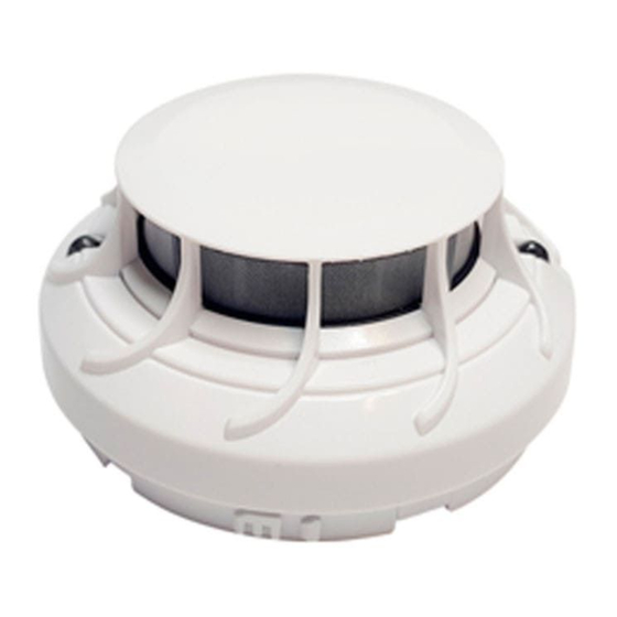
DESCRIPTION
The TC846E1005 is an addressable plug-in type smoke detector suitable
for extremely high sensitivity applications. These sensors are designed for
open area protection and must only be connected to control panels (CIE)
that use a compatible proprietary communication protocol for monitoring
and control. The CIE can communicate with a device using either the
200/500 Series Protocol (CLIP) or Advanced Protocol (AP).
Each device can have its own unique address, which is set using two rotary
code switches on the underside of the product. Two red/green/yellow LEDs
on each sensor provide a local 360
controlled by CIE). Remote LED indicator capability is available as an
optional accessory wired into the standard base terminals.
The detector runs a drift compensation algorithm to determine the level of
dust contamination, and will give an indication to the CIE of the drift level.
This smoke sensor contains an isolator. When installing the device using
the isolator, check the panel documentation for details of how many
isolators can be used on a loop
The TC846E1005 is designed to be backward compatible with the TC846A1005.
SPECIFICATIONS
Operating Voltage Range: 15 to 32 VDC.
Max. Standby Current:
250 μA @24 V & 25
(Red LED blink enabled): 300 μA @24 V & 25
Max. Alarm Current:
add 3 mA @ 24 V & 25
Operating Humidity Range: 10% to 93% Relative Humidity (non condensing)
Power Up Time (max):
3s
Isolator Characteristics
Operating voltage:
≤ 32V
Maximum rated continuous current with the isolator closed (I
Maximum rated isolator current (under short circuit) (I
Max. leakage current (I
max) with the isolator open (isolated state): 12mA
L
Max. series impedance with the isolator closed (Z
This device is tested and certified to EN54-7 and EN54-17.
Avoid locating the sensor in direct sunlight
WIRING
Refer to the installation instructions supplied with the plug-in sensor base
for wiring details.
Note: All wiring must conform to applicable local and national codes and
regulations.
Disconnect loop power before installing sensors
SENSOR INSTALLATION
1. Set the sensor address (see Figure 1) by turning the two rotary switches
on the underside of the sensor (using a screwdriver to rotate the
wheels), selecting a number between 01 and 159. (Note: The number
of addresses available will be dependent on panel capability, check the
panel documentation for information). Record the address on the label
attached to the base.
2. Insert the sensor into the base and rotate clockwise until it locks into place.
3. After all the sensors have been installed, apply power to the system.
4. Test the sensors as described under TESTING.
H200-400-00
Honeywell Building Solutions, Honeywell House, Arlington Business Park, Bracknell, Berkshire, RG12 1EB, UK
HIGH SENSITIVITY SMOKE SENSOR
23 mm
110 g
visible sensor indication (LEDs are
o
C (no comm.)
o
C (comm. every 5s)
o
C (2x red LED on)
o
max): 1A
s
max): 160 m ohm at 15Vdc.
c
Caution
WARNING
TC846E1005
55°C
-10°C
Anti-Tamper Features
These sensors includes a feature that, when activated, prevents removal of
the sensor from the base without the use of a tool. Refer to the installation
instructions for the sensor base for details of how to use this feature.
Dust covers help to protect units during shipping and when first
installed. They are not intended to provide complete protection
against contamination, therefore sensors should be removed before
construction, major re-decoration or other dust producing work is
started. Dust covers must be removed before a system can become
operational.
MAINTENANCE
Before cleaning, disable the system to prevent unwanted alarms:
1. Remove the sensor to be cleaned from its base.
2. Gently release each of the four cover tabs that hold the cover in place
(see Figure 2) and remove the sensor cover.
max): 1A
c
3. Vacuum the outside of the screen carefully without removing it.
4. Remove the screen and air guide assembly by pulling it straight out.
5. Use a vacuum cleaner to remove dust and debris from the sensing
chamber, air guide and inside of the screen.
6. Re-install the assembly by aligning the arrows on the plastic that
indicate the positioning and gently press it home.
7. Re-install the sensor cover. Use the cover tabs and LEDs to align the
cover with the sensor and snap the cover into place.
8. When all sensors have been cleaned, restore power to the loop and
test the sensors as described under TESTING.
Figure 1: Rotary Address Switches
X 10
X 1
CAUTION
Figure 2: Cleaning the Sensor
SENSOR COVER
COVER REMOVAL TABS
SCREEN
AIR GUIDE
OPTICAL SENSING
CHAMBER
E N G L I S H
I 56- 6298- 000
I56-6298-000
Advertisement
Table of Contents

Related Manuals for Honeywell TC846E1005


Summary of Contents for Honeywell TC846E1005
- Page 1 2. Insert the sensor into the base and rotate clockwise until it locks into place. 3. After all the sensors have been installed, apply power to the system. 4. Test the sensors as described under TESTING. H200-400-00 I56-6298-000 Honeywell Building Solutions, Honeywell House, Arlington Business Park, Bracknell, Berkshire, RG12 1EB, UK...
- Page 2 Honeywell House, Arlington Business Park Bracknell, Berkshire, RG12 1EB, UK EN54-7: 2000 / A1: 2002 / A2: 2006 Smoke detectors EN54-17: 2005 Short Circuit Isolators Patents Pending H200-400-00 I56-6298-000 Honeywell Building Solutions, Honeywell House, Arlington Business Park, Bracknell, Berkshire, RG12 1EB, UK...
- Page 3 Stecken Sie den Melder in die sockel und drehen Sie ihn bis zum Einrasten Wenn alle Melderen gereinigt sind, verbinden Sie die Schleife wieder mit im Uhrzeigersinn. dem Netzstrom und testen Sie die Melderen gemäß PRÜFUNG. H200-400-00 I56-6298-000 Honeywell Building Solutions, Honeywell House, Arlington Business Park, Bracknell, Berkshire, RG12 1EB, UK...
- Page 4 Honeywell Control Systems Ltd Honeywell House, Arlington Business Park Bracknell, Berkshire, RG12 1EB, UK EN54-7: 2000 / A1: 2002 / A2: 2006 Rauchmelder EN54-17: 2005 Kurzschlussisolatoren Angemeldete Patente H200-400-00 I56-6298-000 Honeywell Building Solutions, Honeywell House, Arlington Business Park, Bracknell, Berkshire, RG12 1EB, UK...
- Page 5 ; consulter la documentation de la centrale pour tout Emboîter le couvercle à sa place. renseignement). Inscrire l’adresse sur l’étiquette collée sur la socle. H200-400-00 I56-6298-000 Honeywell Building Solutions, Honeywell House, Arlington Business Park, Bracknell, Berkshire, RG12 1EB, UK...
- Page 6 Honeywell House, Arlington Business Park Bracknell, Berkshire, RG12 1EB, UK EN54-7: 2000 / A1: 2002 / A2: 2006 Détecteurs de fume EN54-17: 2005 Isolateurs de court-circuit Brevets en cours H200-400-00 I56-6298-000 Honeywell Building Solutions, Honeywell House, Arlington Business Park, Bracknell, Berkshire, RG12 1EB, UK...
Need help?
Do you have a question about the TC846E1005 and is the answer not in the manual?
Questions and answers