
Related Manuals for MULTIQUIP Whiteman JWN Series


Summary of Contents for MULTIQUIP Whiteman JWN Series
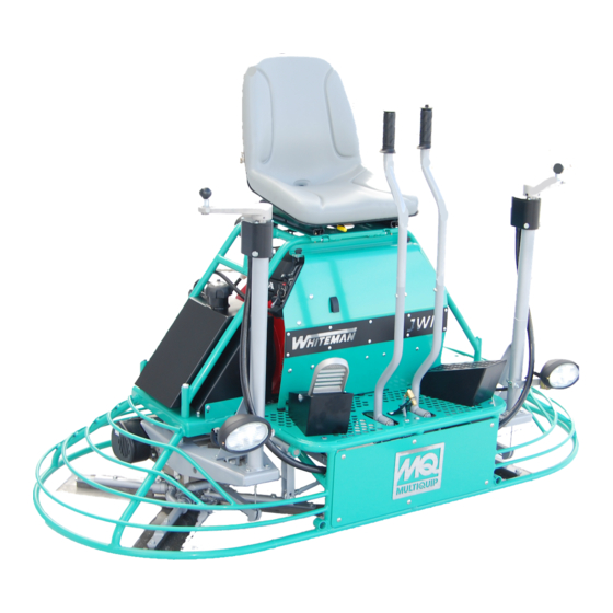
- Page 1 OPERATION AND PARTS MANUAL JWN-SERIES RIDE-ON POWER TROWEL HONDA GX670TAF 24 HP ENGINE Revision #7 (03/02/07) THIS MANUAL MUST ACCOMPANY THE EQUIPMENT AT ALL TIMES. P/N 20214...
- Page 2 We sell worldwide for the brands: Genie, Terex, JLG, MultiQuip, Mikasa, Essick, Whiteman, Mayco, Toro Stone, Diamond Products, Generac Magnum, Airman, Haulotte, Barreto,...
- Page 3 JWN-SERIES — PROPOSITION 65 WARNING Engine exhaust some its constituents, and some dust created by power sanding, sawing, grinding, drillingandotherconstructionactivities contains chemicals known to the State of California to cause cancer, birth defects and other reproductive harm. Some examples of these chemicals are: Leadfromlead-basedpaints.
- Page 4 JWN-SERIES — SILICOSIS/RESPIRATORY WARNINGS WARNING WARNING SILICOSIS WARNING RESPIRATORY HAZARDS Grinding/cutting/drilling of masonry, concrete, metal and Grinding/cutting/drilling of masonry, concrete, metal and other materials with silica in their composition may give other materials can generate dust, mists and fumes off dust or mists containing crystalline silica. Silica is a containing chemicals known to cause serious or fatal basic component of sand, quartz, brick clay, granite and injury or illness, such as respiratory disease, cancer,...
-
Page 5: Table Of Contents
JWN-SERIES — TABLE OF CONTENTS Yoke Assembly ........... 70-71 MQ WHITEMAN — JWN-SERIES Foot Pedals/Throttle Assembly ......72-73 RIDE-ON POWER TROWEL Control Panel Assembly ........74-75 Proposition 65 Warning ..........2 Frame/Fuel Assembly ........76-77 Silicosis/Respiratory Warnings ........3 Battery Assembly ..........78-79 Table of Contents ............ -
Page 6: Training Checklist
JWN-SERIES — TRAINING CHECKLIST TRAINING CHECKLIST This checklist will lists some of the minimum requirements for machine maintenance and operation. Please feel free to detach it and make copies. Use this checklist whenever a new operator is to be trained or it can be used as a review for more experienced operators. -
Page 7: Daily Pre-Operation Checklist
JWN-SERIES — DAILY PRE-OPERATION CHECKLIST DAILY PRE-OPERATION CHECKLIST . l e e L . l e v r o t . l e i t i d t i P o i t t S - t i w o i t i r e l o r o i t... -
Page 8: Safety Message Alert Symbols
JWN-SERIES — SAFETY MESSAGE ALERT SYMBOLS HAZARD SYMBOLS FOR YOUR SAFETY AND THE SAFETY OF OTHERS! Safety precautions should be followed at all times when operating this equipment. Failure to read, understand and Lethal Exhaust Gases comply with the Safety Messages and Operating Instructions could result in injury to yourself and others. - Page 9 JWN-SERIES — SAFETY MESSAGE ALERT SYMBOLS Accidental Starting Respiratory Hazard Accidental starts can cause severe injury or death. ALWAYS place the ON/OFF switch in the OFF position. Disconnect and ground spark plug lead and disconnect negative battery cable ALWAYS wear approved respiratory from battery before servicing.
-
Page 10: Rules For Safe Operation
JWN-SERIES — RULES FOR SAFE OPERATION ■ NEVER operate this equipment when not feeling well due to RULES FOR SAFE OPERATION fatigue, illness or taking medicine. ■ NEVER operate the trowel under the influence of drugs or WARNING WARNING WARNING WARNING WARNING alcohol. - Page 11 JWN-SERIES — RULES FOR SAFE OPERATION ■ NEVER run engine without air filter. Severe engine damage DANGER DANGER DANGER may occur. Service air filter frequently to prevent carburetor DANGER DANGER malfunction. ■ NEVER place your feet or hands inside the guard rings Pay close attention to ventilation when operating the trowel in confined spaces while starting or operating this equipment.
- Page 12 JWN-SERIES — RULES FOR SAFE OPERATION ■ Use chock-blocks at each wheel when parked to prevent Transporting trailer from rolling. ■ ALWAYS shutdown engine before transporting. ■ Use the trailer's swivel jack to adjust the trailer height to a ■ Tighten fuel tank cap securely and close fuel petcock to level position while parked.
- Page 13 JWN-SERIES — RULES FOR SAFE OPERATION Maintenance Safety Emergencies ■ ALWAYS shut down the engine and disconnect battery before ■ ALWAYS know the location of performing service or maintenance functions. Contact with the nearest fire extinguisher . moving parts can cause serious injury. ■...
-
Page 14: Specifications (Trowel)
JWN-SERIES— SPECIFICATIONS (TROWEL) C = 46.75 inches B =39 inches A = 77 inches Figure 1. JWN-Series Dimensions Specifications i r e i f i o i t – A – . n i ) 6 . – B – . -
Page 15: Specifications (Engine)
JWN-SERIES— SPECIFICATIONS (ENGINE) i r e i f i o i t r t S v l a n i l i l o t s i p s i . n i f - f i l o r i A . -
Page 16: General Information
Refer to the engine owner’s manual for specific instructions regarding engine operation. This manual is included with the trowel at the time of shipping. Please contact your nearest Multiquip Dealer for a replacement should the original manual disappear. Blades The blades of the trowel finish the concrete as they are swirled around the surface. -
Page 17: Controls And Indicators
JWN-SERIES — CONTROLS AND INDICATORS Seat – Engine will not start unless operator is seated. Fuel Gauge/Filler Cap - Indicates the amount of fuel in the fuel tank. Remove this cap to add fuel. Steering Control Levers -Directs the unit forward, reverse, left, or right. - Page 18 JWN-SERIES — CONTROLS AND INDICATORS 17. Safety "kill switch" – Shuts down engine when seat is 25. EZ- Mover Boss – Rear attachment point for EZ Mover. empty. Used to transport the trowel. 18. Rear Light – The JWN-Series Ride-On Power Trowel has 26.
-
Page 19: Basic Engine
JWN-SERIES — BASIC ENGINE Figure 4. Engine Controls and Components INITIAL SERVICING Air Filter – Prevents dirt and other debris from entering the The engine (Figure 4) must be checked for proper lubrication and fuel system. Unsnap air filter cover to gain access to filter filled with fuel prior to operation. -
Page 20: New Machine Setup Instructions
JWN-SERIES — NEW MACHINE SETUP INSTRUCTIONS Trowel Pre-Set Up Instructions Seat Assembly The purpose of this section is to assist the user in setting up a The seat is not installed on the trowel for shipping purposes. To NEW trowel. If your trowel is already assembled, (seat, handles, attach the seat perform the following: knobs and battery), this section can be skipped. -
Page 21: Initial Start-Up
JWN-SERIES — INITIAL START-UP The following section is intended as a basic guide to the ride-on Table 4. Recommended Viscosity Grades trowel operation, and is not to be considered a complete guide to concrete finishing. It is strongly suggested that all operators (experienced and novice) read “... - Page 22 JWN-SERIES — INITIAL START-UP 5. When starting a cold engine, pull the choke knob, (Figure 9) out to the closed position. In warm weather or when the FUEL engine is warm, the unit can be started with choke halfway or completely open . Figure 7.
- Page 23 JWN-SERIES — INITIAL START-UP Steering Try adjusting the pitch of the blades. This can be done with the ride-on trowel stopped or while the trowel is moving, Two control levers located in front of the operator’s seat provide whatever feels comfortable. Test the operation of optional directional control for the JWN-SERIES Ride-On Power Trowel.
-
Page 24: Maintenance
JWN-SERIES — MAINTENANCE Maintenance Air Cleaner (Daily) Thoroughly remove dirt and oil from the engine and control When performing any maintenance on the trowel or engine, follow all safety messages and rules for safe operation stated at area. Clean or replace the air cleaner elements as necessary. the beginning of this manual. - Page 25 JWN-SERIES — MAINTENANCE Oil And Fuel Lines CAUTION CAUTION CAUTION CAUTION CAUTION ■ Check the oil and fuel lines and connections regularly for leaks or damage. Repair or replace as necessary. Operating the engine with a blocked grass screen, dirty or plugged cooling fins, and/or cooling shrouds removed, will ■...
- Page 26 JWN-SERIES — MAINTENANCE Checking The Drive Belt The drive belt needs to be replaced as soon as it starts to show signs of wear. Indications of excessive belt wear are fraying, squealing when in use, belts that emit smoke or a burning rubber smell when in use.
- Page 27 JWN-SERIES— MAINTENANCE Insert the 3/4" X 1" X 3-1/4" block between the moveable In the event of a drive belt failure, the spare (replacement) drive belt face and the fixed face of the lower drive pulley. See Figure can be used for quick replacement at the job site to continue trowel 18.
- Page 28 JWN-SERIES— MAINTENANCE CV Joint Bolt (Remove 3 places) New Spare Drive Belt Bolt, Spare Drive Belt Carrier Spare Drive Belt Holder Left Side Gearbox Figure 20. Spare Drive Belt Replacement Spare Drive Belt Replacement Once the CV-joint has been separated from the left-side It will be necessary to disconnect the gearbox, push the CV-joint inward so that a gap exists CV-Joint from the left-side gearbox...
- Page 29 JWN-SERIES— MAINTENANCE As shown in Figure 23, centrifugal force pushes the roller arms (see The JWN-Series Ride-On Power Trowel is equipped with a "Torque Figure 23 below) against the ramp plate, forcing moveable face Converter" which supplies torque to both the left and right gearboxes. toward fixed face squeezing belt.
- Page 30 JWN-SERIES— MAINTENANCE Blade Pitch How It Works (Figure 24) Sometimes it may be necessary to match blade pitch between Condition A: Engine Idling the two sets of blades. There are some signs that this may be Drive Pulley: Small necessary. For example, the differences in pitch could cause a Driven Pulley: Large noticeable difference in finish quality between the two sets of blades.
- Page 31 JWN-SERIES TROWEL — MAINTENANCE Figure 29 illustrates the " correct alignment " for a spider plate Trowel Arm adjustment Procedure (as shipped from the factory). The following procedure should be followed to adjust trowel arms when NOTE it becomes apparent that the trowel is finishing poorly or in need of routine maintenance.
- Page 32 JWN-SERIES TROWEL — MAINTENANCE Trowel Arm Removal Trowel Blade Removal 1. Each trowel arm is held in place at the spider plate by a hex 1. Remove the trowel blades from the trowel arm by removing head bolt (with zerk grease fitting). Remove the hex head the three hex head bolts (Figure 33) from the trowel arm.
- Page 33 JWN-SERIES TROWEL — MAINTENANCE Checking Trowel Arm Straightness 3. Next, check the clearance between the round shaft and the test surface as one of the flat hex sections of the arm rests on Trowel arms can be damaged by rough handling, (such as dropping the test surface.
- Page 34 JWN-SERIES TROWEL — MAINTENANCE 4. Use an allen wrench to tighten the locking bolts securing the trowel arm in place. 5. Adjust the bolt "distance" shown in Figure 36 to match one of the arms. The other arms will be adjusted to match this distance.
- Page 35 JWN-SERIES TROWEL — MAINTENANCE Installing Pans Onto Finisher Blades 1. Lift trowel just enough to slide pan under blades. Lower finisher onto pan with blades (Item #1) adjacent to Z-Clips These round discs sometimes referred to as "pans" attach to the (Item #4).
-
Page 36: Troubleshooting (Engine)
JWN-SERIES TROWEL — TROUBLESHOOTING (ENGINE) . y t l l i n i l n i l n i l l i f n i l t l i f t c i . y r . y r l l i f l l i n i l . - Page 37 JWN-SERIES TROWEL — TROUBLESHOOTING (ENGINE) t l i f l i f i t l a l i , e l l l a i t l i t l y l l y t l . y t l l i f .
-
Page 38: Troubleshooting (Trowel)
JWN-SERIES TROWEL — TROUBLESHOOTING (TROWEL) t i w o i t t i w u f l o i t r o t c t i . y r i l p l i f r e t . l l i t i t i w o i t... - Page 39 JWN-SERIES TROWEL — TROUBLESHOOTING (TROWEL) c e l i r t l a c o i t l c n r e t f o / t i w n i r i r i i t i d h t i .
-
Page 40: Explanation Of Codes In Remarks Column
Multiquip. A blank entry generally indicates that the item is not sold separately or is not sold by Multiquip. Other entries will be clarified in the “Remarks” Column. PAGE 40 — HTN 31V JWN-SERIES • RIDE-ON POWER TROWEL — PARTS AND OPERATION MANUAL — REV. #7 (03/02/07) — PAGE 40... - Page 41 We sell worldwide for the brands: Genie, Terex, JLG, MultiQuip, Mikasa, Essick, Whiteman, Mayco, Toro Stone, Diamond Products, Generac Magnum, Airman, Haulotte, Barreto,...
- Page 42 JWN-SERIES— SUGGESTED SPARE PARTS JWN-SERIES - HONDA GX 670 - TAF 24 HP ENGINE Qty. Description 1 Unit 10031 ....WASHER 1/4 IN. 12548 ....SPRAY PUMP Qty. Description 392292 ....SPRAY NOZZEL 20409 ....TROWEL ARM, LH 2108 ...... CAP, SPRAY TANK 20408 ....TROWEL ARM, RH 2673 ......
-
Page 43: Nameplate And Decals
JWN-SERIES — NAMEPLATE AND DECALS NAMEPLATE AND DECALS “COUNTER “LIFTING POINT” CLOCKWISE” “CHECK” “GEAR DRIVE” “BELT DRIVE” REVERSE VIEW “LIFTING POINT” “LUBRICATION” “LUBRICATION” “LUBRICATION” “CLOCKWISE” “GEAR DRIVE” “CHECK” CUT AND DISCARD DECAL SHEET “KEY” SIDE OF DECAL. INTL STDS ISO P/N 11246 PAGE 42 —... - Page 44 JWN-SERIES — NAMEPLATE AND DECALS NAMEPLATE AND DECALS PART NO. PART NAME QTY. REMARKS 11246 DECAL SET, INTERNATIONAL STDS 13118 DECAL, POWDER COATED 10818 DECAL, MQ-WHITEMAN 24 X 3 2300 DECAL, AL PITCH RH 2332 DECAL, AL PITCH LH 2634 DECAL, SPRING SAFETY 1499 DECAL, MQ-WHITEMAN RED/TOWER...
- Page 45 JWN-SERIES — PIVOT ASSY. (RIGHT/LEFT) PIVOT ASSY. (RIGHT/LEFT) PAGE 44 — HTN 31V JWN-SERIES • RIDE-ON POWER TROWEL — PARTS AND OPERATION MANUAL — REV. #7 (03/02/07) — PAGE 44...
- Page 46 JWN-SERIES— PIVOT ASSY. (RIGHT/LEFT) PIVOT ASSY. (RIGHT/LEFT) PART NO. PART NAME QTY. REMARKS 1023 SCREW, HHC 3/8- 16 X 1-1/4 0166A WASHER, LOCK, 3/8 MED. 2824 BAR, 1” CONTROL PIVOT 20040 ROCKER BLOCK, 1.0 HOLE 10138 SCREW, SHS 5/16- 18 X 5/16 2044 ARM, PIVOT RIGHT HAND 2079...
- Page 47 JWN-SERIES — STEERING HANDLES ASSY. (LEFT/RIGHT) STEERING HANDLES ASSY (LEFT/RIGHT) PAGE 46 — HTN 31V JWN-SERIES • RIDE-ON POWER TROWEL — PARTS AND OPERATION MANUAL — REV. #7 (03/02/07) — PAGE 46...
- Page 48 JWN-SERIES — STEERING HANDLES ASSY. (LEFT/RIGHT) STEERING HANDLES ASSY (LEFT/RIGHT) PART NO. PART NAME QTY. REMARKS 0189 GRIP, HANDLE 2063 ROD END, 3/8-24 MALE RH 10130-1 HANDLE, TUBE 2197 NUT, ACORN, 1/4-20 0424 SCREW HHC 1/4-20 X 1-1/4 11079-1 HANDLE, STEERING, LOWER 2196 SPACER, 1/2 X .402 X 1/4L 2064...
- Page 49 JWN-SERIES — STEERING CONTROL ASSY. (LEFT/RIGHT) STEERING CONTROL ASSY. (LEFT/RIGHT) DETAIL A SEE DETAIL A SIDE VIEW PART OF RIGHT SIDE PIVOT ASSEMBLY PART OF LEFT SIDE PIVOT ASSEMBLY LEFT SIDE STEERING HANDLES. SEE PAGE 48. RIGHT SIDE ADJUST STEERING STOP SCREWS TO LIMIT TRAVEL PREVENTING CV JOINT FROM BOTTOMING.
- Page 50 JWN-SERIES — STEERING CONTROL ASSY. (LEFT/RIGHT) STEERING CONTROL ASSY. (LEFT/RIGHT) PART NO. PART NAME QTY. REMARKS 11146 NUT, HEX JAM 1/2-20 PLTD 11142 ROD END, 1/2-20 MALE RH EM963105 SCREW, HHC 1/-13 X 2........4..REPLACES P/N 6159A 10176 NUT, NYLOC 1/2-13 12625 ASSIST ASSEMBLY, STEERING 0447...
- Page 51 JWN-SERIES — GEARBOX ASSY (RIGHT) GEARBOX ASSY. (RIGHT) PAGE 50 — HTN 31V JWN-SERIES • RIDE-ON POWER TROWEL — PARTS AND OPERATION MANUAL — REV. #7 (03/02/07) — PAGE 50...
- Page 52 JWN-SERIES — GEARBOX ASSY (RIGHT) GEARBOX ASSY. (RIGHT) PART NO. PART NAME QTY. REMARKS 20065 SHAFT, GEARBOX INPUT W/FAN 5031A SCREW, RHM 1/4- 20 X 1/2 0948 WASHER, FLAT, 1/4 SAE 12981 SHROUD, GB FIN COVER, RIGHT 20353 GEAR BOX 1-1/8 SHAFT 0121A FITTING, PLUG 3/8MP SQUARE HEAD 10989...
- Page 53 JWN-SERIES — GEARBOX ASSY. (LEFT) GEARBOX ASSY. (LEFT) PAGE 52 — HTN 31V JWN-SERIES • RIDE-ON POWER TROWEL — PARTS AND OPERATION MANUAL — REV. #7 (03/02/07) — PAGE 52...
- Page 54 JWN-SERIES — GEARBOX ASSY. (LEFT) GEARBOX ASSY. (LEFT) PART NO. PART NAME QTY. REMARKS 20065 SHAFT, GEARBOX INPUT W/FAN 5031A SCREW, RHM 1/4- 20 X 1/2 0948 WASHER, FLAT, 1/4 SAE 12982 SHROUD, GB FIN COVER, LEFT 20353 GEAR BOX 1-1/8 SHAFT 0121A FITTING, PLUG 3/8MP SQUARE HEAD 10989...
- Page 55 JWN-SERIES — TWIN PITCH HANDLE ASSY. (LEFT/RIGHT) TWIN PITCH HANDLE ASSY. (LEFT/RIGHT) LEVER ASSEMBLY, ITEM 26 INCLUDES ITEMS WITHIN OUTLINE. KNOB KIT P/N 2737 (ITEM 27) INCLUDES ITEMS 1,2,4, AND 5. RIGHT SIDE PITCH HANDLE IS IDENTICAL TO LEFT SIDE PITCH HANDLE UNLESS CONTINUED ON PAGE 67.
- Page 56 JWN-SERIES — TWIN PITCH HANDLE ASSY. (LEFT/RIGHT) TWIN PITCH HANDLE ASSY. (LEFT/RIGHT) PART NO PART NAME QTY. REMARKS 1 #$ 4403 CRANK KNOB 2 #$ 3231 SPACER 1615 CRANK LEVER 4 #$ 1733 HARDENED WASHER 5 #$ 1616 SHOULDER BOLT 6 +% 2620 SCREW, BHC 10 –...
- Page 57 JWN-SERIES — TWIN PITCH TOWER ASSY. (LEFT/RIGHT) TWIN PITCH TOWER ASSY. (LEFT/RIGHT) LEFT RIGHT LEFT RIGHT RIGHT SIDE TOWER ASSEMBLY P/N 10421 AND LEFT SIDE TOWER ASSEMBLY P/N 10392 CONTINUED ON PAGE 68 INCLUDES ALL ITEMS WITHIN OUTLINE. , ITEM 31. KNOB KIT P/N 2737, SEE PAGE 64 ITEM 26.
- Page 58 JWN-SERIES — TWIN PITCH TOWER ASSY. (LEFT/RIGHT) TWIN PITCH TOWER ASSY. (LEFT/RIGHT) PART NO PART NAME QTY. REMARKS 1 (LT) 10392 TOWER ASSY. , LEFT TPC ....1 .. INCLUDES ITEMS W/+ 1 (RT) 10421 TOWER ASSY. , RIGHT TPC ....1 .. INCLUDES ITEMS W/ 2 +% 10512 RING, SNAP, TRUARC 5160 –...
-
Page 59: Twin Pitch Tower Assembly (Left/Right)
JWN-SERIES— TWIN PITCH MITER BOX ASSY. (LEFT/RIGHT) TWIN PITCH MITER BOX ASSY. (LEFT/RIGHT) CONTINUED FROM , ITEM 19 SEE PAGE 66 TYPICAL BOTH LEFT AND RIGHT SIDES CONTINUED FROM , ITEM 13 SEE PAGE 66 COMPLETE MITER PART OF LEFT SIDE TWIN BOX ASSEMBLY PITCH TOWER ASSEMBLY TO RIGHT... - Page 60 JWN-SERIES— TWIN PITCH MITER (LEFT/RIGHT) TWIN PITCH MITER BOX ASSY. (LEFT/RIGHT) PART NO. PART NAME QTY. REMARKS 0181B WASHER, LOCK 1/4 MED 1536 U-JOINT, PITCH CONTROL 1162 A CAP, GREASE ZERK 10548 TUBE, PITCH CONTROL 1586 PIN ROLL 1/8 x 3/4 ..... 11 ..QTY INCLUDES USAGE ON BOTH TWIN PITCH ..............
- Page 61 JWN-SERIES — DRIVE ASSY. DRIVE ASSY. PAGE 60 — HTN 31V JWN-SERIES • RIDE-ON POWER TROWEL — PARTS AND OPERATION MANUAL — REV. #7 (03/02/07) — PAGE 60...
-
Page 62: Drive Assembly
JWN-SERIES — DRIVE ASSY. DRIVE ASSY. PART NO. PART NAME QTY. REMARKS 20077 DRIVE ASSEMBLY ..........1 ..INCLUDES ITEMS W/% 20186 PLATE, BEARING MOUNT 10909 KEY, 3/16 X 11/16 0126 KEY, WOODRUFF #9 2090 RING, SNAP TRUARC #5100- 106 1146 SCREW, FHSC 5/16- 18 X 1 NYLOC 2037... - Page 63 JWN-SERIES — MUFFLER/BELT ASSY. MUFFLER/BELT ASSY. PAGE 62 — HTN 31V JWN-SERIES • RIDE-ON POWER TROWEL — PARTS AND OPERATION MANUAL — REV. #7 (03/02/07) — PAGE 62...
- Page 64 JWN-SERIES — MUFFLER/BELT ASSY. MUFFLER/BELT ASSY. PART NO. PART NAME QTY. REMARKS 20216 ENGINE, HONDA 24 HP GX670 20336 MUFFLER, 24 HONDA 0160C WASHER, LOCK 5/16 MEDIUM 2299 SCREW, HHC M8-1.25 X 16MM 0300A SCREW, HHC 5/16-18 X 2 19470 WASHER, FLAT 5/16 USS 2655 HOUR METER...
- Page 65 JWN-SERIES — BELTGUARD ASSY. BELT GUARD ASSY. PAGE 64 — HTN 31V JWN-SERIES • RIDE-ON POWER TROWEL — PARTS AND OPERATION MANUAL — REV. #7 (03/02/07) — PAGE 64...
- Page 66 JWN-SERIES — BELTGUARD ASSY. BELT GUARD ASSY. PART NO. PART NAME QTY. REMARKS 20100 BELT GUARD 11819 SCREW, HHC W/WASHER 1/4-20 X 3/4 11534 NUT, U-TYPE 1/4-20 JWN- SERIES • RIDE-ON POWER TROWEL — PARTS AND OPERATION MANUAL — REV. #7 (03/02/07) — PAGE 65...
- Page 67 JWN-SERIES — SPIDER ASSY. (RIGHT) SPIDER ASSY. (RIGHT) PAGE 66 — HTN 31V JWN-SERIES • RIDE-ON POWER TROWEL — PARTS AND OPERATION MANUAL — REV. #7 (03/02/07) — PAGE 66...
- Page 68 JWN-SERIES — SPIDER ASSY. (RIGHT) SPIDER ASSY. (RIGHT) PART NO. PART NAME QTY. REMARKS 1154A PLATE, WEAR THRUST COLLAR 10793 THRUST COLLAR W/ BUSHING ......1 ..INCLUDES ITEMS W/+ 12208 WEAR RING 12778 BEARING, THRUST 6013 2RSW/ FLANGE 1141 KEY, 5/16 SQ.
- Page 69 JWN-SERIES — SPIDER ASSY. (LEFT) SPIDER ASSY. (LEFT) PAGE 68 — HTN 31V JWN-SERIES • RIDE-ON POWER TROWEL — PARTS AND OPERATION MANUAL — REV. #7 (03/02/07) — PAGE 68...
- Page 70 JWN-SERIES — SPIDER ASSY. (LEFT) SPIDER ASSY. (LEFT) PART NO. PART NAME QTY. REMARKS 1154A PLATE, WEAR THRUST COLLAR 10793 THRUST COLLAR W/ BUSHING ......1 ..INCLUDES ITEMS W/+ 12208 WEAR RING 12778 BEARING, THRUST 6013 2RSW/ FLANGE 1141 KEY, 5/16 SQ.
- Page 71 JWN-SERIES — YOKE ASSY. YOKE ASSY. PAGE 70 — HTN 31V JWN-SERIES • RIDE-ON POWER TROWEL — PARTS AND OPERATION MANUAL — REV. #7 (03/02/07) — PAGE 70...
- Page 72 JWN-SERIES — YOKE ASSY. YOKE ASSY. PART NO. PART NAME QTY. REMARKS 9027 YOKE 0683 PIN, COTTER 3/32 X 3/4 10136 WASHER, FLAT 3/8 SAE 9028 PIN, YOKE 1116 NUT, BRASS JAM 5/16-18 2008 CABLE ASSEMBLY 25.63 JWN- SERIES • RIDE-ON POWER TROWEL — PARTS AND OPERATION MANUAL — REV. #7 (03/02/07) — PAGE 71...
- Page 73 JWN-SERIES — FOOT PEDALS/THROTTLE ASSY. FOOT PEDALS/THROTTLE ASSY. PAGE 72 — HTN 31V JWN-SERIES • RIDE-ON POWER TROWEL — PARTS AND OPERATION MANUAL — REV. #7 (03/02/07) — PAGE 72...
- Page 74 JWN-SERIES — FOOT PEDALS/THROTTLE ASSY. FOOT PEDALS/THROTTLE ASSY. PART NO. PART NAME QTY. REMARKS 20348 CABLE, CONTROL 10-32 X 33 LONG 2754 ADAPTER, THROTTLE SPRING, LONG 2753 SPRING, THROTTLE RETURN 2755 ADAPTER, THROTTLE SPRING, SHORT 0937 NUT, HEX 10-32 ZINC PLTD 10019 NUT, NYLOC 10- 32 2203...
- Page 75 JWN-SERIES — CONTROL PANEL ASSY. CONTROL PANEL ASSY. PART OF SEAT/FRAME ASSEMBLY BLK/YEL WIRE FROM BREAKER TERMINAL “B” TO HONDA BLK/YEL WIRE. BLK/YEL WIRE FROM BREAKER TERMINAL “A” TO HONDA BLK/YEL WIRE. WHITE WIRE FROM LIGHT SWITCH TERMINAL “D” TO BREAKER TERMINAL “B”.
-
Page 76: Control Panel Assembly
JWN-SERIES — CONTROL PANEL ASSY. CONTROL PANEL ASSY. PART NO. PART NAME QTY. REMARKS 2673 CIRCUIT BREAKER, 30A, 12V 4682 SWITCH,TOGGLE ELECTRIC #9061 20344 WIRE ASSEMBLY, 16 GA. X 5” 10019 NUT, NYLOC 10- 32 20342 WIRE ASSEMBLY, 16 GA. X 7” 20343 WIRE ASSEMBLY, 16 GA. - Page 77 JWN-SERIES — FRAME/FUEL ASSY. FRAME/FUEL ASSY. PAGE 76 — HTN 31V JWN-SERIES • RIDE-ON POWER TROWEL — PARTS AND OPERATION MANUAL — REV. #7 (03/02/07) — PAGE 76...
- Page 78 JWN-SERIES — FRAME/FUEL ASSY. FRAME/FUEL ASSY. PART NO. PART NAME QTY. REMARKS 12404 TANK, FUEL FIVE GALLON 11418 FUEL CAP/GAUGE (10.5) 19633 BUSHING, RUBBER FUEL FITTING, 90 4BARB- 4BARB FUEL 19473 CLAMP, WORM HOSE, #4 (1/4- 5/8) 60013 HOSE, RUBBER FUEL 0.25 ID ......2 ....SOLD IN FT. LENGTHS 20907 FUEL PUMP ASSEMBLY 4514...
- Page 79 JWN-SERIES — BATTERY ASSY. BATTERY ASSY. PAGE 78 — HTN 31V JWN-SERIES • RIDE-ON POWER TROWEL — PARTS AND OPERATION MANUAL — REV. #7 (03/02/07) — PAGE 78...
- Page 80 JWN-SERIES — BATTERY ASSY. BATTERY ASSY. PART NO. PART NAME QTY. REMARKS 2509 WING NUT, PLATED 10031 WASHER, EXT SHKP 1/4 20356 BRACKET BATTERY HOLD- DOWN 20194 BOLT, BATTERY HOLD DOWN 2449 BOX, BATTERY GR UI 2762 BOOT, TERMINAL 0131A SCREW, HHC 1/4- 20 X 3/4 BATTERY, GR.
- Page 81 We sell worldwide for the brands: Genie, Terex, JLG, MultiQuip, Mikasa, Essick, Whiteman, Mayco, Toro Stone, Diamond Products, Generac Magnum, Airman, Haulotte, Barreto,...
- Page 82 JWN-SERIES — SPRAY ASSY. SPRAY ASSY. STEERING HANDLES, SEE PAGE 48. PAGE 80 — HTN 31V JWN-SERIES • RIDE-ON POWER TROWEL — PARTS AND OPERATION MANUAL — REV. #7 (03/02/07) — PAGE 80...
- Page 83 JWN-SERIES — SPRAY ASSY. SPRAY ASSY. PART NO. PART NAME QTY. REMARKS 392292 NOZZLE, SPRAY 2898 WASHER, BONDED NEOPRENE 1 X 1/2 11222 MOUNT, SPRAY NOZZLE 1023 SCREW, HHC 3/8-16 X 1 1/4 10136 WASHER, FLAT 3/8 SAE 10024 NUT, NYLOC 1/4-20 2912 FITTING, 90 4BARB-1/4FP 8128...
- Page 84 JWN-SERIES — LIGHT ASSY. LIGHT ASSY. PAGE 82 — HTN 31V JWN-SERIES • RIDE-ON POWER TROWEL — PARTS AND OPERATION MANUAL — REV. #7 (03/02/07) — PAGE 82...
-
Page 85: Light Assembly
JWN-SERIES—LIGHT ASSY. LIGHT ASSY. PART NO. PART NAME QTY. REMARKS 2896 LIGHT KIT ASSEMBLY 5283 NUT, NYLOC 5/16-18 0300B WASHER, FLAT 5/16 SAE 2531 BRACKET, LIGHT SIDE 2534 CLAMP ASSEMBLY, MUFFLER 1-3/4 JWN- SERIES • RIDE-ON POWER TROWEL — PARTS AND OPERATION MANUAL — REV. #7 (03/02/07) — PAGE 83... - Page 86 JWN-SERIES — SEAT FRAME ASSY. SEAT FRAME ASSY. PAGE 84 — HTN 31V JWN-SERIES • RIDE-ON POWER TROWEL — PARTS AND OPERATION MANUAL — REV. #7 (03/02/07) — PAGE 84...
- Page 87 JWN-SERIES — SEAT FRAME ASSY. SEAT FRAME ASSY. PART NO. PART NAME QTY. REMARKS 2351 SEAT 2421 SEAT PLATE 0161C WASHER, LOCK, 5/16 MEDIUM 1237 SCREW, SHC, 5/16- 18 X 7/8 NYLOC 2889 FRAME, SEAT 11644 SCREW, HHC, WASHER 10- 32 X 5/8 10237 WASHER, EXT.
- Page 88 JWN-SERIES — EZ-MOVER ASSY. EZ-MOVER ASSY. PAGE 86 — HTN 31V JWN-SERIES • RIDE-ON POWER TROWEL — PARTS AND OPERATION MANUAL — REV. #7 (03/02/07) — PAGE 86...
- Page 89 JWN-SERIES — EZ-MOVER ASSY. EZ-MOVER ASSY. PART NO. PART NAME QTY. REMARKS 0189 HAND GRIP 2336 HANDLE, UPPER 1869 PIN, SNAP 7170 CLIP 11684 AXLE, DOLLY 10440 WHEEL & TIRE 8151 WASHER, FLAT 3/4 SAE 0183 PIN, COTTER 10446 WASHER, FLAT 3/4 0655 SCREW, HHCS 5/16-18 X 3/4 0161C...
- Page 90 HONDA GX-670 — AIR CLEANER ASSY. AIR CLEANER ASSY. PAGE 88 — HTN 31V JWN-SERIES • RIDE-ON POWER TROWEL — PARTS AND OPERATION MANUAL — REV. #7 (03/02/07) — PAGE 88...
- Page 91 HONDA GX-670 — AIR CLEANER ASSY. AIR CLEANER ASSY. PART NO. PART NAME QTY. REMARKS 17210ZJ1841 ELEMENT COMP., AIR CLEANER 17218ZJ1840 FILTER, OUTER 17219ZJ1840 CLIP, AIR CLEANER 17220ZN1000 HOUSING COMP., AIR CLEANER 17229ZN1000 SEAL, AIR CLEANER HOUSING 17230ZJ1840 COVER ASSEMBLY, AIR CLEANER 17233ZJ1840 SEAL, AIR CLEANER COVER 17234ZJ1840...
- Page 92 HONDA GX-670 — CAMSHAFT ASSY. CAMSHAFT ASSY. PAGE 90 — HTN 31V JWN-SERIES • RIDE-ON POWER TROWEL — PARTS AND OPERATION MANUAL — REV. #7 (03/02/07) — PAGE 90...
-
Page 93: Camshaft Assembly
HONDA GX-670 — CAMSHAFT ASSY. CAMSHAFT ASSY. PART NO. PART NAME QTY. REMARKS 12209ZE8003 SEAL, VALVE STEM 14100ZJ1842 CAMSHAFT ASSEMBLY ......1 ....INCLUDES ITEMS W/% 14410ZJ1840 ROD, PUSH 14431ZE2010 ARM, VALVE ROCKER 14451ZE1013 PIVOT, ROCKER ARM 14568ZJ1841 SPRING, WEIGHT RETURN 14576ZJ1840 PIN, DECOMPRESSION 14711ZE3000... - Page 94 HONDA GX-670 — CARBURETOR ASSY. CARBURETOR ASSY. PAGE 92 — HTN 31V JWN-SERIES • RIDE-ON POWER TROWEL — PARTS AND OPERATION MANUAL — REV. #7 (03/02/07) — PAGE 92...
-
Page 95: Carburetor Assembly
HONDA GX-670 — CARBURETOR ASSY. CARBURETOR ASSY. PART NO. PART NAME QTY. REMARKS 12357ZJ1840 TUBE, BREATHER 15772551000 CLIP, BREATHER TUBE 16010ZN1003 GASKET SET 16011ZN1003 VALVE, FLOAT 16013ZN1003 FLOAT SET 16015ZN1003 CHAMBER SET, FLOAT ......1 ....INCLUDES ITEMS W/ 16024ZN1003 SCREW SET, DRAIN 16028ZN1003 SCREW SET... - Page 96 HONDA GX-670 — CONTROL ASSY. CONTROL (2) ASSY. PAGE 94 — HTN 31V JWN-SERIES • RIDE-ON POWER TROWEL — PARTS AND OPERATION MANUAL — REV. #7 (03/02/07) — PAGE 94...
-
Page 97: Control Assembly
HONDA GX-670 — CONTROL ASSY. CONTROL (2) ASSY. PART NO. PART NAME QTY. REMARKS 16263883W10 JOINT, ROD 16500ZJ1850 CONTROL ASSEMBLY ........ 1 ....INCLUDES ITEMS W/ 16534ZN1000 SPRING, STARTER 16551ZJ1840 ARM, GOVERNOR 16555ZN1000 ROD, GOVERNOR 16561ZN1800 SPRING, GOVERNOR (MANUAL) 16562ZN1000 SPRING, THROTTLE RETURN 16570ZJ1850 ARM COMP., CONTROL... - Page 98 HONDA GX-670 — CONTROL BOX ASSY. CONTROL BOX ASSY. PAGE 96 — HTN 31V JWN-SERIES • RIDE-ON POWER TROWEL — PARTS AND OPERATION MANUAL — REV. #7 (03/02/07) — PAGE 96...
- Page 99 HONDA GX-670 — CONTROL BOX ASSY. CONTROL BOX ASSY. PART NO. PART NAME QTY. REMARKS 31612ZE2003 CASE, CONTROL 31614ZE2003 BRACKET, CASE MOUNTING 31620ZG5003 RECTIFIER ASSEMBLY REGULATOR 20A 32103759000 BRACKET, WIRE HARNESS CLIP 32105ZJ1800 SUB- WIRE HARNESS ASSEMBLY 32340ZJ1841 BOX ASSEMBLY CONTROL ........ 1 ....INCLUDES ITEMS W/ 32345ZJ1811 PANEL COMP., CONTROL 32349ZJ1840...
- Page 100 HONDA GX-670 — CRANKCASE COVER ASSY. CRANKCASE COVER ASSY. PAGE 98 — HTN 31V JWN-SERIES • RIDE-ON POWER TROWEL — PARTS AND OPERATION MANUAL — REV. #7 (03/02/07) — PAGE 98...
- Page 101 HONDA GX-670 — CRANKCASE COVER ASSY. CRANKCASE COVER ASSY. PART NO. PART NAME QTY. REMARKS 11300ZJ1840 COVER ASSEMBLY, CRANKCASE (Q- TYPE) ..1 ..INCLUDES ITEMS W/ 11381ZJ1840 GASKET, CASE COVER 15124ZJ1000 COVER ASSEMBLY, OIL PUMP 15124ZJ1003 ROTOR, OIL PUMP (OUTER) 15232ZJ1000 SPRING RELIEF VALVE 15348ZJ1840...
- Page 102 HONDA GX-670 — CRANKSHAFT ASSY. CRANKSHAFT ASSY. PAGE 100 — HTN 31V JWN-SERIES • RIDE-ON POWER TROWEL — PARTS AND OPERATION MANUAL — REV. #7 (03/02/07) — PAGE 100...
- Page 103 HONDA GX-670 — CRANKSHAFT ASSY. CRANKSHAFT ASSY. PART NO. PART NAME QTY. REMARKS 13310ZN1000 CRANKSHAFT COMP., T-TYPE 90401ZJ1000 WASHER, CRANKSHAFT THRUST JWN- SERIES • RIDE-ON POWER TROWEL — PARTS AND OPERATION MANUAL — REV. #7 (03/02/07) — PAGE 101...
- Page 104 HONDA GX-670 — CYLINDER BARREL ASSY. CYLINDER BARRELASSY. PAGE 102 — HTN 31V JWN-SERIES • RIDE-ON POWER TROWEL — PARTS AND OPERATION MANUAL — REV. #7 (03/02/07) — PAGE 102...
- Page 105 HONDA GX-670 — CYLINDER BARREL ASSY. CYLINDER BARREL ASSY. PART NO. PART NAME QTY. REMARKS 12000ZN1010 CYLINDER ASSEMBLY ........1 ..INCLUDES ITEMS W/ 12356ZJ1000 COVER, BREATHER 12358ZJ1000 GASKET, BREATHER COVER 12372ZE2300 VALVE, BREATHER 15558ZJ010AH VALVE, DRAIN 14 X 1.5 (OPTIONAL) 16541ZJ1840 SHAFT, GOVERNOR ARM 31511ZJ1000...
- Page 106 HONDA GX-670 — CYLINDER HEAD ASSY. CYLINDER HEAD ASSY. PAGE 104 — HTN 31V JWN-SERIES • RIDE-ON POWER TROWEL — PARTS AND OPERATION MANUAL — REV. #7 (03/02/07) — PAGE 104...
- Page 107 HONDA GX-670 — CYLINDER HEAD ASSY. CYLINDER HEAD ASSY. PART NO. PART NAME QTY. REMARKS 11911ZJ1840 HANGER, ENGINE 12204ZE2306 GUIDE, VALVE (OS), OPTIONAL 12205ZJ1405 GUIDE, EX. VALVE (OS), OPTIONAL 12210ZJ1840 CYLINDER HEAD COMP. #1 ........ 1 ..INCLUDES ITEMS W/ 12216ZE2300 CLIP, VALVE GUIDE 12220ZJ1840...
- Page 108 HONDA GX-670 — FAN COVER ASSY. FAN COVER ASSY. PAGE 106 — HTN 31V JWN-SERIES • RIDE-ON POWER TROWEL — PARTS AND OPERATION MANUAL — REV. #7 (03/02/07) — PAGE 106...
- Page 109 HONDA GX-670 — FAN COVER ASSY. FAN COVER ASSY. PART NO. PART NAME QTY. REMARKS 16715ZJ1850 COVER, FUEL PUMP, MANUAL CONTROL 19611ZJ1840ZA COVER, FAN *NH1* (BLACK) 19612ZJ1840 PLATE, RIGHT SIDE 19614ZJ1840 PLATE, LEFT SIDE 19631ZJ1840 SHROUD, RIGHT 19632ZN1000 SHROUD, LEFT 33713GC2000 COLLAR B, TAIL LIGHT 80101310000...
- Page 110 HONDA GX-670 — FLYWHEEL ASSY. FLY WHEEL ASSY. PAGE 108 — HTN 31V JWN-SERIES • RIDE-ON POWER TROWEL — PARTS AND OPERATION MANUAL — REV. #7 (03/02/07) — PAGE 108...
- Page 111 HONDA GX-670 — FLYWHEEL ASSY. FLY WHEEL ASSY. PART NO. PART NAME QTY. REMARKS 19511ZJ1000 FAN, COOLING 19513ZJ1000 PLATE, COOLING FAN SETTING 28452ZJ1811 GRID, SCREEN P.T.O. (OPTIONAL) 28454ZJ1801 HOLDER, SCREEN GRID, OPTIONAL 31110ZJ1840 FLY WHEEL COMP. 90201ZG3000 NUT, FLANGE 20MM 90401ZG3000 WASHER 20MM 90741ZE2000...
- Page 112 HONDA GX-670 — FUEL PUMP ASSY. FUEL PUMP ASSY. PAGE 110 — HTN 31V JWN-SERIES • RIDE-ON POWER TROWEL — PARTS AND OPERATION MANUAL — REV. #7 (03/02/07) — PAGE 110...
- Page 113 HONDA GX-670 — FUEL PUMP ASSY. FUEL PUMP ASSY. PART NO. PART NAME QTY. REMARKS 16700ZL8003 PUMP ASSEMBLY, FUEL 16711ZJ1840 STAY, FUEL PUMP 16851ZN1000 TUBE, FUEL 16852ZJ1840 TUBE B, FUEL 16882ZJ1840 TUBE, DIAPHRAGM 16910ZE8015 FILTER COMP., FUEL 19111MF5000 GROMMET, RESERVE TANK 90014952000 BOLT, FLANGE 6 X 14 90517SA0003...
- Page 114 HONDA GX-670 — IGNITION COIL ASSY. IGNITION COIL ASSY. PAGE 112 — HTN 31V JWN-SERIES • RIDE-ON POWER TROWEL — PARTS AND OPERATION MANUAL — REV. #7 (03/02/07) — PAGE 112...
- Page 115 HONDA GX-670 — IGNITION COIL ASSY. IGNITION COIL ASSY. PART NO. PART NAME QTY. REMARKS 30500ZJ1841 COIL ASSEMBLY R. IGNITION 30518ZJ1000 GROMMET, IGNITION WIRE 30550ZJ1841 COIL ASSEMBLY, L.. IGNITION 30700ZJ1841 CAP ASSEMBLY, NOISE SUPPRESSOR 31630ZJ1801 COIL ASSEMBLY, CHARGE 12V/20A 31740ZJ1841 DIODE ASSEMBLY, ENGINE STOP .....
- Page 116 HONDA GX-670 — LABELS ASSY. LABELS ASSY. PAGE 114 — HTN 31V JWN-SERIES • RIDE-ON POWER TROWEL — PARTS AND OPERATION MANUAL — REV. #7 (03/02/07) — PAGE 114...
- Page 117 HONDA GX-670 — LABELS ASSY. LABELS ASSY. PART NO. PART NAME QTY. REMARKS 87101ZN1000 MARK, EMBLEM 87152ZN1000 LABEL, SPECIFICATION G X 670 87532ZJ1840 MARK, THROTTLE INDICATION JWN- SERIES • RIDE-ON POWER TROWEL — PARTS AND OPERATION MANUAL — REV. #7 (03/02/07) — PAGE 115...
- Page 118 HONDA GX-670 — OIL COOLER ASSY. OIL COOLER ASSY. PAGE 116 — HTN 31V JWN-SERIES • RIDE-ON POWER TROWEL — PARTS AND OPERATION MANUAL — REV. #7 (03/02/07) — PAGE 116...
- Page 119 HONDA GX-670 — OIL COOLER ASSY. OIL COOLER ASSY. PART NO. PART NAME QTY. REMARKS 11513MN5300 COLLAR 12MM 15605ZN1000 COOLER ASSEMBLY, OIL ........1 ..INCLUDES ITEMS W/ 15610ZN1000 COOLER COMP., OIL 15613ZN1000 GRILLE, OIL COOLER 15614ZN1003 HOSE A, OIL 15616ZN1003 HOSE B, OIL 15676ZN1000...
- Page 120 HONDA GX-670 — PISTON + CONNECTING ROD ASSY. PISTON + CONNECTING ROD ASSY. PAGE 118 — HTN 31V JWN-SERIES • RIDE-ON POWER TROWEL — PARTS AND OPERATION MANUAL — REV. #7 (03/02/07) — PAGE 118...
- Page 121 HONDA GX-670 — PISTON + CONNECTING ROD ASSY. PISTON + CONNECTING ROD ASSY. PART NO. PART NAME QTY. REMARKS 13010ZJ1841 RING SET, PISTON STD. 13011ZJ1841 RING SET, PISTON OS 0.25 (OPTIONAL) 13012ZJ1841 RING SET, PISTON OS 0.50 (OPTIONAL) 13013ZJ1841 RING SET, PISTON 0.75 (OPTIONAL) 13101ZN1000 PISTON STD.
- Page 122 HONDA GX-670 — STARTER MOTOR ASSY. STARTER MOTOR ASSY. PAGE 120 — HTN 31V JWN-SERIES • RIDE-ON POWER TROWEL — PARTS AND OPERATION MANUAL — REV. #7 (03/02/07) — PAGE 120...
- Page 123 HONDA GX-670 — STARTER MOTOR ASSY. STARTER MOTOR ASSY. PART NO. PART NAME QTY. REMARKS 30201PH9004 RING, SNAP (DENSO) 30202PZ1003 COLLAR SET, CLUTCH STOP 31200ZJ1841 MOTOR ASSEMBLY STARTER ......1 ..INCLUDES ITEMS W/ 31203PH9004 LEVER, PINION DRIVE 31204ZJ1H01 SWITCH ASSEMBLY, MAGNET 31206ZG4801 ARMATURE COMP.
- Page 124 We sell worldwide for the brands: Genie, Terex, JLG, MultiQuip, Mikasa, Essick, Whiteman, Mayco, Toro Stone, Diamond Products, Generac Magnum, Airman, Haulotte, Barreto,...
Need help?
Do you have a question about the Whiteman JWN Series and is the answer not in the manual?
Questions and answers