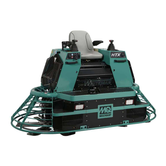
MULTIQUIP WHITEMAN Series Setup And Adjustment
Hydraulic ride-on trowel psi 2.4l engine gas and propane engine
Hide thumbs
Also See for WHITEMAN Series:
- Operation and parts manual (64 pages) ,
- Operation manual (52 pages) ,
- Operator's manual (40 pages)
Table of Contents
Advertisement
Quick Links
Advertisement
Table of Contents

Subscribe to Our Youtube Channel
Related Manuals for MULTIQUIP WHITEMAN Series


Summary of Contents for MULTIQUIP WHITEMAN Series
- Page 1 SERIES MODEL HTXG6DF HYDRAULIC RIDE-ON TROWEL (PSI 2.4L ENGINE) Gas and Propane Engine Revision #0 (11/12/15) To find the latest revision of this publication, visit our website at: www.multiquip.com THIS MANUAL MUST ACCOMPANY THE EQUIPMENT AT ALL TIMES. PN: 42638...
-
Page 2: Table Of Contents
TABLE OF CONTENTS HTXG6DF Trowel Machine Information And Maintenance Log .... 3 Secondary Hydraulic Fill Procedures ....22 Safety Information ..........4-9 Machine Pressure Adjustment......22 Tools Needed ............10 Charge Pressure Adjustment ......22 Machine Information ..........11 Pitch Pressure Check ........23 Model .............. -
Page 3: Machine Information And Maintenance Log
MACHINE INFORMATION AND MAINTENANCE LOG Technician__________________________________e Date:___________________________ Machine Information MODEL LH Motor Serial No. Machine Serial No. RH Motor Serial No. Engine Serial No. Program ID Pump Serial No. Program Version Machine Setup and Calibration Information Hydraulic Pressure Settings Calibration Point 1 Point 2 (Hydraulic Oil Temperature Below 125 °F) -
Page 4: Safety Information
SAFETY INFORMATION Do not operate or service the equipment before reading Potential hazards associated with the operation of this the entire manual. Safety precautions should be followed equipment will be referenced with hazard symbols which at all times when operating this equipment. may appear throughout this manual in conjunction with Failure to read and understand the safety safety messages. - Page 5 „ NEVER use accessories or attachments that are not „ Avoid wearing jewelry or loose fi tting clothes that may recommended by Multiquip for this equipment. Damage snag on the controls or moving parts as this can cause to the equipment and/or injury to user may result.
- Page 6 SAFETY INFORMATION TROWEL SAFETY NOTICE „ ALWAYS keep the machine in proper running condition. DANGER „ Fix damage to machine and replace any broken parts „ Engine fuel exhaust gases contain poisonous carbon immediately. monoxide. This gas is colorless and odorless, and can cause death if inhaled.
- Page 7 SAFETY INFORMATION BATTERY SAFETY NOTICE „ NEVER run engine without an air fi lter or with a dirty air DANGER fi lter. Severe engine damage may occur. Service air fi lter „ DO NOT drop the battery. There is a possibility that the frequently to prevent engine malfunction.
- Page 8 SAFETY INFORMATION TRANSPORTING SAFETY TOWING SAFETY CAUTION CAUTION „ NEVER allow any person or animal to „ Check with your local county or state safety stand underneath the equipment while towing regulations, in addition to meeting lifting. Department of Transportation (DOT) Safety Towing Regulations, before towing „...
- Page 9 SAFETY INFORMATION „ Trailer should be adjusted to a level position at all times when towing. „ Raise and lock trailer wheel stand in up position when towing. „ Place chock blocks underneath wheel to prevent rolling while parked. „ Place support blocks underneath the trailer’s bumper to prevent tipping while parked.
-
Page 10: Tools Needed
TOOLS NEEDED The specialized tools listed in Table 1 are required to maintain and service the HTXG6DF ride-on trowel. Fleet technicians and servicing dealers must have these tools for efficient unit setup and component calibration. Table 1. Setup, Calibration, and Diagnostic Tools TOOL DESCRIPTION PART NO. -
Page 11: Machine Information
MACHINE INFORMATION 2. Pump Serial Number — located on sticker on pump NOTICE (Figure 3). Lower number is the serial number. The following machine information should be recorded on Machine Information and Maintenance Log for unit service tracking and for filing any warranty claims. MODEL 1. -
Page 12: General Procedures
GENERAL PROCEDURES REMOVE SETUP JUMPER NOTICE (If installed). These general procedures will be referenced in other sections throughout the manual. 1. Remove Setup Jumper (P/N: 42538) from J5 of main harness. SETUP JUMPER INSTALLATION 2. Re-install Plug (P/N: 42440) on J5 of main harness. NOTICE Machine must be secured prior to installation. -
Page 13: Initial Check And Adjustments
INITIAL CHECK AND ADJUSTMENTS PRELIMINARY CHARGE PRESSURE ADJUSTMENT FLUID FILL AND CHECK Hydraulic Oil Check NOTICE Skipping this step during initial set-up may cause 1. To check the hydraulic oil level, place the trowel on a machine to inadvertently move during further steps, secure flat surface with the engine stopped. -
Page 14: Engine Oil
INITIAL CHECK AND ADJUSTMENTS Engine Oil Engine Coolant 1. Ensure engine is level. 1. Verify that the radiator drain cock is closed. 2. Remove the oil filler cap (item 4 in Figure 7). 2. Remove radiator cap. 3. Pour engine coolant (Dexcool or long life coolant only) slowly into the radiator until it is even with the lip of the engine coolant filler port (Figure 8). -
Page 15: Service Tool License Key Request Form
For maintaining proper records and qualifying our service dealers, this form must be complete and returned to Multiquip Technical Support office to receive the Whiteman Service Tool application file and License key. -
Page 16: Service Tool Setup And Connection
3. The WST file will be sent to you as an attachment to is not populated an e-mail. Whiteman Service Tool 4. Open the e-mail sent by Multiquip and click on the attachment. On the drop-down menu, select "Save Target As" (Figure 10). Application File... - Page 17 Figure 14. WST License Manager • License Key Install • Click on License 11. Input the license key obtained from Multiquip Manager (Figure 15) and click "OK". cense key and click OK. • Input you license key and click OK.
-
Page 18: Laptop Configuration
LAPTOP CONFIGURATION CONNECTION PROCEDURE 4. When the CAN Gateway cable is connected to the laptop for the first time, it is necessary to install the NOTICE CAN driver software. The installation screen will appear (Figure 19). Click "Next" to install the software WST –... -
Page 19: Loading Software
LOADING SOFTWARE FILE DOWNLOAD PROCEDURE 6. Select target ECU by clicking on the only ECU shown then click "OK" (Figure 24). 1. Make sure laptop and machine are connected. See Connection Procedure section. 2. Turn key on machine to RUN position but DO NOT start machine. -
Page 20: Parameter File Transfer
LOADING SOFTWARE PARAMETER FILE TRANSFER 9. If prompted for application type enter “42003” and click “OK” button (Figure 27). 1. Turn key to RUN position but DO NOT start machine. 2. Click on "Stop Logging" button (Figure 29). Figure 27. Application Type Screen 10. -
Page 21: Machine Setup And Calibration
MACHINE SETUP AND CALIBRATION CALIBRATE FOOT PEDAL Calibration 1. Turn key to ON position but DO NOT start machine. 1. Set sensor zero position default: 2. Click “CALIBRATION” button on machine setup page. a. Ensure that foot pedal is fully released. 3. -
Page 22: Secondary Hydraulic Fill Procedures
MACHINE SETUP AND CALIBRATION SECONDARY HYDRAULIC FILL PROCEDURES 1. Disable cold start. 2. With machine off, install gauge capable of reading 300 NOTICE psi to Charge Or Pitch pressure test port (Figure 33). Once the oil heats up, any oil expansion will go up the overflow hose and into the fluid expansion tank. -
Page 23: Pitch Pressure Check
MACHINE SETUP AND CALIBRATION 10. Return engine rpm to idle. 3. Using a 1/4" allen wrench, adjust the small hex nut within the larger hex jam nut. 11. Turn off machine and remove gauge. 4. Tighten 3/4" jam nut. Pitch Pressure Check 5. -
Page 24: Trowel Speed Adjustment/Setup
MACHINE SETUP AND CALIBRATION 7. Adjust to proper steering pressure: 245 psi ± 10 psi (Cold Oil) 235 psi ± 10 psi (Hot Oil) 8. Retighten jam nut. 9. Return engine to idle. 10. Turn off machine and remove gauge. 11. -
Page 25: Left Side Trowel Speed Adjustment
MACHINE SETUP AND CALIBRATION 4. Adjust speed limit screw and tighten jam nut (Figure 38). 3. Adjust trowel arm connecting rod on the pump actuating lever and tighten jam nuts (Figure 39). Jam Nut Figure 39. Adjusting Right Side Trowel Speed Figure 38. -
Page 26: Pitch Setup
MACHINE SETUP AND CALIBRATION 5. Click “Calibration” button in STROKE SENSOR section 7. Set Sensor full position default: (Figure 40). a. Have an operator fully depress pedal and hold at full blade speed. b. Read % Sensor Voltage. c. Round value to nearest percent and enter in CALB POINT 2 DEFAULT. -
Page 27: Flatten Blades
MACHINE SETUP AND CALIBRATION Leading Edge Height Adjustment Flatten Blades 1. If leading edge height is within limits (2.000” ± .060”) 1. Adjust blade pitch adjustment bolts as necessary to for left and right side, then no adjustment is needed. ensure machine operates smoothly (Figure 42). -
Page 28: Set Zero Pitch Cylinder Stops
MACHINE SETUP AND CALIBRATION Set Zero Pitch Cylinder Stops Pitch Sensor Calibration CAUTION 1. Flatten blades (bottom out the pitch cylinders). Machine movement will occur during this step. All 2. Turn machine off. guards should be in place. Keep fingers, hands, hair, 3. - Page 29 MACHINE SETUP AND CALIBRATION g. Click on "Hard Ext." Button to fully extend pitch cylinders. 3.25” GAUGE h. Remove gauge. 6. Set Calibration Point 2. a. Install 2.25” Gauge P/N 32000 over both Left and Right Cylinders as shown in Figure 47. b.
- Page 30 MACHINE SETUP AND CALIBRATION a. Click on "Hard Ret." Button to fully retract cylinders, ensure yoke is against zero pitch stop. b. Click on "Soft Ext." button, and wait until yoke is pressing against thrust collar. Engine speed must be at low idle to avoid moving the thrust collar. c.
-
Page 31: Inspection
INSPECTION FLUID LEVELS 3. Hydraulics • Spot check paint marks on fittings. Record the following fluid levels on Machine Information and • Ensure that there are no leaks. Maintenance Log in Inspection section. Refer to Fluid Fill and Check section for procedure. 4. -
Page 32: Static Blade Pitch Drift Test
INSPECTION STATIC BLADE PITCH DRIFT TEST 1. Switch smart pitch switch to off position. 2. Bring machine up to temperature. This will be indicated by “Cold Start” (aux 1) lamp turning off. 3. Choose one blade from each spider and mark with small X to identify. -
Page 33: Fuse Information
FUSE INFORMATION Refer to Figure 51 for location on fuse panel. Table 3. Fuses Fuse Number Fuse Rating, Amps Connector Pin # Description RH Hyd Cooler Fan Open Foot Platform Lights Left Lights Right Lights Accessory Power Port Spray Pumps LH Hyd Cooler Fan Seat Switch Left Hand Switches... - Page 34 © COPYRIGHT 2015, MULTIQUIP INC. Multiquip Inc , the MQ logo and the Whiteman logo are registered trademarks of Multiquip Inc. and may not be used, reproduced, or altered without written permission. All other trademarks are the property of their respective owners and used with permission.
Need help?
Do you have a question about the WHITEMAN Series and is the answer not in the manual?
Questions and answers