Table of Contents
Advertisement
Quick Links
PR 5210 Transmitter Series
PR 5210/00 Profibus Transmitter
PR 5210/10 Digital Process Transmitter
PR 5210/11 Profibus Transmitter
Operating Manual
Operating manual
for PR 5210
Sartorius Hamburg GmbH , Meiendorfer Str. 205, D 22145 Hamburg, Germany
Tel: +49.40.67960.303 Fax: +49.40.67960.383
9499 050 52103
Release: 3
(without Analog Output)
Edition 3
11.11.2004
Advertisement
Table of Contents

Related Manuals for Sartorius PR 5210 Series


Summary of Contents for Sartorius PR 5210 Series
- Page 1 PR 5210/10 Digital Process Transmitter PR 5210/11 Profibus Transmitter (without Analog Output) Operating Manual Operating manual 9499 050 52103 Edition 3 11.11.2004 for PR 5210 Release: 3 Sartorius Hamburg GmbH , Meiendorfer Str. 205, D 22145 Hamburg, Germany Tel: +49.40.67960.303 Fax: +49.40.67960.383...
- Page 2 Any information in this document is subject to change without notice and does not represent a commitment on the part of SARTORIUS. This product should be operated only by trained and qualified personnel. In correspondence concerning this product the type, name and release number as well as all license numbers in relation to the product have to be quoted.
-
Page 3: Table Of Contents
Data in the PR5210 ............................20 4.3.2 Archive data in the PC............................20 ............................20 RINT DATA SET ............................21 ELECT LANGUAGE ...............................21 TATUS LINE ADU................................22 4.7.1 Weighing point calibration..........................22 4.7.2 Weighing point configuration........................24 ..............................26 ARAMETER 4.8.1 Analog output ..............................26 Sartorius... - Page 4 Register 2: Status of state controlled action bits ................... 51 6.2.4 Register 3: Status of transition controlled action bits................51 6.2.5 Register 4: Calibration information, error byte..................52 6.2.6 Register 5: Transmitter type and version....................53 6.2.7 Register 6: Board number ..........................53 Sartorius...
- Page 5 Weight..................................70 7.11 ..............................70 CCESSORIES 7.12 ..............................70 PTIONS APPENDIX............................71 EC D ......................71 ECLARATION OF ONFORMITY EC T PTB D03-09-025 ................74 APPROVAL ERTIFICATE ..............................75 PARE PARTS ...........75 XAMPLE PRINT OUT CONFIGURATION AND CALIBRATION DATA PARAMETERS DP........................76 FILE FOR ROFIBUS INDEX..............................77 Sartorius...
-
Page 7: Safety Hints, Electrical Protection Class
Check the contents of the consignment for completeness and note whether any damage has occurred during transport. If the content is incomplete or damaged, a claim must be filed with the carrier immediately and the Sartorius Hamburg sales or service organization must be informed to permit repair or replacement of the unit. -
Page 8: Protective Earth
1.4 Repair and maintenance Repairs are subject to checking and can be carried out only at Sartorius Hamburg GmbH, Hamburg. In case of defect or functional trouble, please, contact your local Sartorius organization for repair. When returning the instrument for repair, an exact and complete fault description must be supplied. -
Page 9: Pr 5210 Transmitter Series
This version has got an Analog Output, but no Profibus connection, the respective menus in the operating tools are adapted to it. 2.1.3 PR 5210/11 Version (without Analog Output) This version has got a Profibus connection, but no Analog Output, the respective menus in the operating tools are adapted to it. Sartorius... -
Page 10: Transmitter Survey
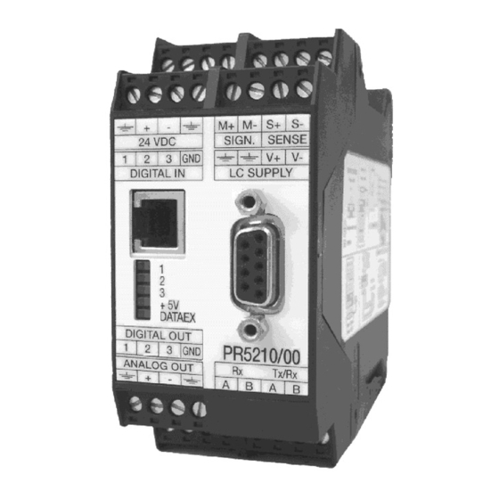
Communication protocols: • RS 232 for PC • Profibus-DP (PR 5210/00 and PR 5210/11 only) • RS 485/ RS 422 for remote display 2.3 Label on the housing The wiring principle is located at the side of the housing: Sartorius... -
Page 11: Housing
PR 5210 Operating Manual PR 5210 Transmitter Series 2.4 Housing To open the housing, press the four closings (two on each side). During assembly, take care of the earth connection in the bottom of the housing. Sartorius... -
Page 12: Connections
2.5 Connections 2.5.1 Load cell connection The cable colours shown in this chapter are of Sartorius load cells series PR 62XX. Before connection of other types, carefully read the instructions concerning cable colours of the load cell / platform. 2.5.1.1 Connection in 6-wire technique See label on the housing (chapter 2.3) and the documentation for the cable junction box. - Page 13 PR 1626/60 manual. For connection via PR 1626/60 the solder jumper J403 has to be closed If the PR 16126/ 60 has to be used with MX 8 : closed, please contact Sartorius Hamburg technical support for further INFO! Sartorius...
-
Page 14: Rs 232 Interface
(+ at RxA - at RxB) Connection remote display PR 1627 or remote terminal PR 1628/00, -/60 or -/24 (with PR 1604 Interface) From the connected terminal / display the following operations are possible via pushbuttons: Test Set tare Reset tare Set zero Sartorius... -
Page 15: Analog Output (Pr 5210/00 And Pr 5210/10 Only)
150 m (current output) 0/4 ... 20mA Analog signal, current output. The current is supplied directly from the terminals. 0 ... 10V Analog signal, voltage output. The voltage level corresponds to the voltage drop at the 500 Ohm (10 ppm/K) resistor. Sartorius... -
Page 16: Opto Inputs
The profibus connection is done via the 9 pole female connector on the front. Transmitter is the only Transmitter is not the only / Signal or the last slave on the bus not the last slave on the bus RxD/TxD-P CNTR-P DGND RxD/TxD-N Sartorius... -
Page 17: Operating Elements
Error 3 Error 6 Arithmetic (negative) Overload (> 36 mV) Sense control Flash. 1Hz Flash. 1Hz Altern. flash 1 Hz Flash. 1Hz Flash. 1Hz Altern. flash 1 Hz Flash. 1Hz Flash. 1Hz Flash. 1Hz Flash. 1Hz Altern. flash 1 Hz Sartorius... -
Page 18: Cal Switch
If a new calibration is started, the calibration data are set to default (The parameters remain unchanged). Calibration data and parameters are stored in EAROM and kept in case of power failure or if the instrument is disconnected from power supply. Sartorius... -
Page 19: Setup And Configuration
Start the program PR 5210-WIN Configurator 03.00 Setup.exe Follow the instructions given Select the destination directory (e.g. C:\Programs\Sartorius\PR 5210) After successful installation the message: Installation finished will appear Start the program in the previously defined directory: ConfigureIt!.exe The program will automatically look for the COM port where the PR 5210 is... -
Page 20: Load And Store Setup And Configuration
Save Dataset Store the modified data under a name different from DEFAULT.DAT 4.4 Print data set Print Dataset The current calibration data and all parameters are printed on the printer assigned as standard printer. See example in chapter 8.4. Sartorius... -
Page 21: Select Language
The program could establish a communication connection over COM1 with a PR5210 with the version 2.09.15. A data set for the device type PR5210/00 is loaded. The transmitter PR5210 had the boardnumber 4294967294. The actual weight is 67 kg. Sartorius... -
Page 22: Adu
The stepwidth (scale interval) which is valid for the total scale range has to be selected: 1, 2, 5, 10, 20, 50, default is 1. 4.7.1.3 Resolution magnifier: During calibration the display resolution (scale interval) can be increased by factor 10. Sartorius... - Page 23 (M+, M-). For the Span a measuring signal of 12 mV could be calculated. At full scale deflection the measuring signal is deadload value + Span = 18 mV (M+, M-) Sartorius...
-
Page 24: Weighing Point Configuration
If Weight & Measure ('legal for trade') is set to on, parameters are not automatically set to fulfill the requirements! Please refer to the EN 45501 and the Type-approval Certificate. The Weight & Measure mode has to be set before a calibration is started. Default is off. Sartorius... - Page 25 For W&M applications, the correction must not be above 0.5 d/sec. • The automatic zero tracking stepwidth must be smaller than the standstill range also for non W&M applications. This function is only valid, if Zerotrack repeat is not set to 0!, see chapter 4.7.2.13. Sartorius...
-
Page 26: Parameter
Analog output is not used transparent Analog output is controlled via PLC (e.g. to set the mixer speed) gross Gross weight value is linked to the output Net weight value is linked to the output (if not tared : gross) Sartorius... -
Page 27: Profibus Address
Enter the weight value at which the analog output shall show 20 mA. 4.8.2 Profibus Address The address on the profibus has to be defined here, valid addresses are in the range 1, 2 ... 126. Default is 10. Sartorius... -
Page 28: Bus Size
4.7.2.9) set tare The transmitter will be switched to net mode. (standstill has to be fulfilled, else standstilltimeout will be given, see chapter 4.7.2.5 , 4.7.2.7 and 4.7.2.9) reset tare The transmitter will be switched to gross mode Sartorius... -
Page 29: Limits
If the limit values for ON and OFF are equal, the limit output switches on, if the weight increases over the value and switches off, if the weight decreases below the value. Default values for Limit1 – Limit 3 are 0 kg. Sartorius... -
Page 30: Calibrate
(FSD) and will be entered. Press [Set Span]. By entering by mV/V, enter the mV/V value for the full span (zero to full scale deflection value (FSD)). 5. step: Save calibration. Sartorius... -
Page 31: Analog Output Adaption
E.g. 4.002mA.. Press [next]. 3. step: The analog output is set to 20mA. Measure the current at the receiver side and enter the value of the measured current. E.g. 20.003mA.. Press [next]. The current is now corrected to 4.000mA and 20.000mA. Sartorius... -
Page 32: Status
Tare and reset tare Set zero 4.11.1 Analog part weight status Display Error 3 Error 7 negative positive Error 2 Error 3 (SKE) ±0,25d overload Below0 CZERO aboveFSD InZSR DeadLd±InsideZSR ADUERR ADUERR ADUERR W&M off DIMM W&M on DIMM DIMM Sartorius... -
Page 33: Sma Protocol
<_ _ _ _ _0.000>; <_ _ _ _11.120>; <_ _ _ _ -1.000>; <- - - - - - - - - -> <yyyyyy> Text field of printable ASCII characters used to convey scale information. This field will not exceed a maximum of 25 characters. <uuu> Unit-of-Measure abbreviation. This field is always 3 characters long with a trailing space(s) when appropriate. Sartorius... -
Page 34: Scale Command Set
For this function the standstill condition of the scale must be fullfilled. The maximum wait time for standstill could set with the 'Standstill time-out'. See 4.7.2.9 <LF><Z><r><n><m><f><xxxxxx.xxx><uuu><CR> For detail see chapter 5.4.1 Standard Scale Response Message If the scale is not inside the zero set range, an error message is generated. Sartorius... -
Page 35: Request Scale To Tare
For detail see chapter 5.4.5 About ‘A’ and ‘B’ Command Response 5.3.11 About Scale Scroll Command: <LF>B<CR> Response: The scale will send the rest of the ABout the scale data. <LF><MFG>:<yyyyyy><CR> For detail see chapter 5.4.5 About ‘A’ and ‘B’ Command Response Sartorius... -
Page 36: Scale Information
Scale Repeats weight and status information continuously until another command is received. <LF><s><r><n><m><f><xxxxxx.xxx><uuu><CR> For detail see chapter 5.4.1 Standard Scale Response Message Depending on the used baud rate, the following approximately repetition times of response messages are possible: 19200 Bd 100ms 9600 Bd 110ms 4800 Bd 170ms Sartorius... -
Page 37: Scale Response Messages
<LF> <_> <1> <N> <_> <_> <_ _ _ _ 100000> <lb_> <CR> <LF>H<CR> <LF> <_> <1> <g> <_> <_> <_ _ _ _5.0025> <lb_> <CR> <LF>Z<CR> <LF> <Z> <1> <G> <_> <_> <_ _ _ _ _0.000> <lb_> <CR> Sartorius... -
Page 38: Unrecognized Command Response
Start of About response <xxx> About field descriptor is fixed at 3 characters, is left justified, filled with blanks on the right side. Following fields are send: “SMA” compliance level/revision (response of ‘A’ command) “MFG” manufacturer (response of 1st ‘B’ command) Sartorius... -
Page 39: Scale Information 'I' And 'N' Command Response
(1, 2, etc.); revision= (1.0, 1.1, etc.) <CR> End of About response Example: Command Response <LF> A <CR> <LF>SMA:1/1.0 <CR> <LF> B <CR> <LF>MFG:Sartorius <CR> <LF> B <CR> <LF>MOD:PR5210 <CR> <LF> B <CR> <LF>REV:02.09.9 <CR> <LF> B <CR> <LF>SN_:148388723 <CR> <LF> B <CR> <LF>END: <CR>... -
Page 40: Communication Error Handling
ASCII ‘?’. Upon error discovery the host can then decide which course of action to take to re-affirm or re-establish proper communications with the scale. Sartorius... -
Page 41: Profibus Interface
Profibus-DP Profibus interface 8-byte write 8-byte read window window Data and functions in PR 5210 Interface • Weight data • Weight status protocol • Limit values • Calibration • Configuration • Digital Inputs • Digital outputs • Analog output Sartorius... -
Page 42: Write Window (Input Area)
2. Write value in byte 0 to 3. Write_Value_Select 3. Write register number in byte 5 ( Write_Active 4. Wait, until = 1 (acknowledges data reception) Write_Value_Select Write_Active 5. Write 0 into byte 5 ( ) -> will go to 0. Sartorius... -
Page 43: Description Of I/O Area (Read/ Write Window)
The weight value has exceeded the measuring range, no valid weight data are given (Gross>FSD+Overload) AboveFSD The weight value has exceeded FSD, but is still within FSD+Overload. (Gross <= FSD+Overload) AduError Error in AD conversion.(Details are available at register 1, Read_Value_Select = 1) Sartorius... - Page 44 The Test mode will be finished SetTest The Test mode will be started. Now the test number is shown, by reading the gross weight. ResTare Tare will be reset SetTare The transmitter will be tared SetZero The transmitter will be set to zero Sartorius...
-
Page 45: Register Read And Write Via Profibus
To reset, the bit number + 128 (208..255) is written to Write_Value_Select. The Write_Value itself is not relevant. Master Transmitter Register number in Write_Value_Select Write Write_Value to selected register Set bit Write_Active Wait until Write_Active is set Write 0 in Write_Value_Select Reset bit Write_Active Sartorius... - Page 46 IF error occurs: Set bit CmdError and byte LastError Reset bit CmdBusy Wait until CmdBusy is reset Test bit CmdError: If set, read LastError (see chapter 6.1.5.1) This is valid for taring, standstill, zero setting, calibrating, reading and writing of parameters via Profibus Sartorius...
- Page 47 Error The gross value (hex:000004D2 <=> 1234) could be read out from Bytes 0...3. If the status-Bits 'Overload', 'Test Active' or 'Adu Error' is set, the read out value is not valid. Negative values are given in two's complement. Sartorius...
-
Page 48: Parameter Read And Write Via Profibus
4, byte 3. Set parameter P20 to 3 (SaveAndExit) Data are stored in the non-volatile EAROM (method see chapter 6.1.6.1) Set parameter P20 to 4 (UndoAndQuitCal) All modified data are erased, continue with the (method see chapter 6.1.6.1) previously stored data. Sartorius... - Page 49 Set parameter P20 to 2 (default = factory Default data are taken as calibration data. data) All ADU data will be reset. See chapter 4.7 (method see chapter 6.1.6.1) Set parameter P20 to 3 (SaveAndExit) Data are stored in the non-volatile EAROM (method see chapter 6.1.6.1) Sartorius...
-
Page 50: Profibus Register
117) 'Power failure reset' the bit PowerFail is reset. TestActiv Analog test is aktive CalChanged Calibration mode is active or calibration data have been changed. FSD has to be read again to reset this bit. TareActiv Transmitter has beeen tared Sartorius... -
Page 51: Register 2: Status Of State Controlled Action Bits
Bit 0 Byte 0 Byte 1 Byte 2 GetFixTare SetFixTare ResetPWF ResetTest SetTest ResetTare SetTare SetZero Byte 3 SaveConfig GetParam SetParam SaveProcess ResetError 6.2.4 Register 3: Status of transition controlled action bits Only reading is allowed, it is always 0 Sartorius... -
Page 52: Register 4: Calibration Information, Error Byte
30 = weight smaller than deadload 102, 103 = EAROM error (command SaveProcess, register 2) 104 = wrong access code 106 = baudrate of remote display cannot be altered 107 = no standstill at Getfixtare 108 = parameter not valid (at entering via PLC) Sartorius... -
Page 53: Register 5: Transmitter Type And Version
Actual net value, if tared, else gross Register10 Actual tare value, if tared, else 0 Register11 Reserved Register12 Reserved Register13 Reserved Register14 Full scale deflection FSD Register15 Reserved (free) 6.2.10 Register 20 and 21: Parameter channel (read/write) Register 20 Parameter value Register 21 Parameter index Sartorius... -
Page 54: Register 22
Register 92 GetParam Read parameter (parameter R21 to R20) Register 93 SaveConfig The configuration parameter will be stored to EAROM analog output (parameter 1...3) I/O parameter (parameter 4, 6) input/output configuration (parameter 5, 7) access control parameter (parameter 99) Sartorius... -
Page 55: Register 112
SetParam Register 124 GetParam Register 125 SaveConfig To prevent the EAROM from beeing written too often, the writing rate for taring and zero setting should not be shorter than 15 seconds, for configuration data not shorter than 5 minutes. Sartorius... -
Page 56: Profibus Parameter Numbers
Bit 2 Bit 1 Bit 0 Byte 0 WEIGHT MSB Byte 1 "" Byte 2 "" Byte 3 WEIGHT LSB The WEIGHT value is stored at which the analog output is giving 0 or 4 mA. Default = 0 Sartorius... - Page 57 Output 3 , default = 0 Description Value transparent* aduerr Limit1 Limit2 Limit3 tare active * Transparent mode means, that the PLC is writing to the outputs directly. Limit(x) means, that the transmitter is writing the limit result to the outputs directly. Sartorius...
- Page 58 Byte 1 Input 1 default 0 Byte 2 Input 2 default 0 Byte 3 Input 3 default 0 Description Value none set Zero set Tare reset Tare The PLC can read the status of the inputs at any time. Sartorius...
-
Page 59: Calibration
(e.g. 250,0kg) • Parameter 24 = 2500 250,0kg • Parameter 20 = 3 save and exit calibration After each step, the error has to be tested under each circumstances. Sartorius... - Page 60 All changes since start calibration are not valid. CalActiv is reset. SetDefaultSpan To be used to start a calibration: All calibration data are reset, scale in status calibrated FSD = 3000 kg, stepwidth = 1, span = 1.000000 mV/V, deadload = 0.000000 mV/V. Sartorius...
-
Page 61: Adu Parameter
Write only Bit 7 Bit 6 Bit 5 Bit 4 Bit 3 Bit 2 Bit 1 Bit 0 Byte 0 Byte 1 Byte 2 Byte 3 At writing to this parameter, the actual weight will be stored as deadload. Sartorius... - Page 62 SPAN in mV/V (value in mV/V )*10 6.3.3.7 Parameter P27: CalcTest Write only Bit 7 Bit 6 Bit 5 Bit 4 Bit 3 Bit 2 Bit 1 Bit 0 Byte 0 Byte 1 Byte 2 Byte 3 Calculate testvalue Sartorius...
- Page 63 Parameter P43: Test mode Bit 7 Bit 6 Bit 5 Bit 4 Bit 3 Bit 2 Bit 1 Bit 0 Byte 0 Byte 1 Byte 2 Byte 3 MODE MODE 0 = absolute, 1 = relative, default = 0 Sartorius...
- Page 64 Bit 7 Bit 6 Bit 5 Bit 4 Bit 3 Bit 2 Bit 1 Bit 0 Byte 0 Byte 1 Byte 2 RANGE MSB Byte 3 RANGE LSB RANGE 0 ... 500.00 d default = 50 d Value = d*100 Sartorius...
- Page 65 Parameter P51: Overload Bit 7 Bit 6 Bit 5 Bit 4 Bit 3 Bit 2 Bit 1 Bit 0 Byte 0 OVL MSB Byte 1 "" Byte 2 "" Byte 3 OVL LSB Overload in d 0..9999999 default = 9 d Sartorius...
-
Page 66: Parameter P99: Access Code
P99. Parameter P99 can always be written. To activate the protection P99 has to be set to –1 again. If CODE is set to 0, no access check is done. Sartorius... -
Page 67: Technical Data
U= ± 6 VDC for I = 160 mA, protected by multifuses Load cell supply circuit 12V DC for max. 8 load cells each with 650 Ω for max. 4 load cells each with 350 Ω Max. load > 75 Ω Sartorius... -
Page 68: Rs 232 Interface
9.6, 19.2, 93.75, 187.5, 500 [kBps], 1.5, 3.0, 6.0, 12.0 [MBps], automatic detection Buffer size 8 bytes I/O data 8 bytes UserPrm Sync Freeze Clear Set-Slave-Add 7.8 Power supply Power voltage 24 VDC +10% / -15% Power consumption 8.2 W Sartorius... -
Page 69: Environmental Effects
Ripple on DC input voltage EN 61000-4-17 +20 / -15%. 5% ripple Voltage variations EN 61000-4-11 40% / 0% Voltage dips EN 61000-4-11 20 ms 7.9.3 RF interference suppression Electromagnetic emission acc. To EN 55011 group 1, limit value class B Sartorius... -
Page 70: Mechanical Data
WIN tool to configure/operate the transmitter from PC (Windows 98, _NT, - 2000, -XP) on CD-ROM Cable PC (DB9 f) to PR 5210 (RJ-12 m), length 2.0 m. 7.12 Options 9499 050 52103. Operation manual on paper (English), order no. 9499 050 52183. Operation manual on paper (German), order no. Sartorius... -
Page 71: Appendix
PR 5210 Operating Manual Appendix PPENDIX 8.1 EC Declaration of Conformity EG-Konformitätserklärung EC-Declaration of Conformity Monat/Jahr: 02/2003 month/year: Hersteller: Sartorius Hamburg GmbH Manufacturer: Anschrift: Meiendorfer Str. 205 Address: D-22145 Hamburg Deutschland Produktbezeichnung: PR 5210/00 Product name: Profibustransmitter Das bezeichnete Produkt stimmt mit folgenden Vorschriften der Europäischen Richtlinien überein:... - Page 72 Appendix PR 5210 Operating Manual EG-Konformitätserklärung EC-Declaration of Conformity Monat/Jahr: 02/2003 month/year: Hersteller: Sartorius Hamburg GmbH Manufacturer: Anschrift: Meiendorfer Str. 205 Address: D-22145 Hamburg Deutschland Produktbezeichnung: PR 5210/10 Product name: Process Transmitter , Analog Output Das bezeichnete Produkt stimmt mit folgenden Vorschriften der Europäischen Richtlinien überein:...
- Page 73 PR 5210 Operating Manual Appendix EG-Konformitätserklärung EC-Declaration of Conformity Monat/Jahr: 02/2003 month/year: Hersteller: Sartorius Hamburg GmbH Manufacturer: Anschrift: Meiendorfer Str. 205 Address: D-22145 Hamburg Deutschland Produktbezeichnung: PR 5210/11 Product name: Process Transmitter , Profibus Das bezeichnete Produkt stimmt mit folgenden Vorschriften der Europäischen Richtlinien überein:...
-
Page 74: Ec Type-Approval Certificate Ptb D03-09-025
Appendix PR 5210 Operating Manual 8.2 EC Type-approval Certificate PTB D03-09-025 Sartorius... -
Page 75: Spare Parts
Limit 1 on 0 kg Limit 1 off 0 kg Limit 2 on 0 kg Limit 2 off 0 kg Limit 3 on 0 kg Limit 3 off 0 kg Value for 4 mA 4,000 Value for 20 mA 20,000 Sartorius... -
Page 76: Gsd File For Profibus Dp
Appendix PR 5210 Operating Manual 8.5 GSD file for Profibus DP ;======================================================================= ;GSD-Datei für den Profibus Transmitter PR5210 ;Stand 03.08.2004 - Sartorius Hamburg Version:V1.11 ;======================================================================= #Profibus_DP Vendor_Name = "Sartorius Hamburg GmbH" Model_Name = "PR5210 Profibus Transmitter" Revision = "Version 1.1"... -
Page 77: Index
RS 485 / 422 Interface..........14 Factory settings............... 18 Scale status............... 50 SMA..................33 GSD file for Profibus DP..........76 Spare parts................ 75 Sprachauswahl ............20, 21 IO-Status bits for reading..........50 Weight error..............17 Weight status indication..........17 Write window ..............42 LEDs..................17 Sartorius... - Page 80 Sartorius Hamburg GmbH Meiendorfer Straße 205 22145 Hamburg, Germany Tel.: +49.40.67960.303 Fax: +49.40.67960.383 www.sartorius.com Sartorius Hamburg GmbH All rights are strictly reserved Printed in Germany...
Need help?
Do you have a question about the PR 5210 Series and is the answer not in the manual?
Questions and answers