Table of Contents
Advertisement
Quick Links
Instrument Manual
Ethernet Transmitter Series PR 5220
PR 5220/00 Ethernet Transmitter
PR 5220/01 Ethernet Transmitter with ProfiBus
PR 5220/04 Ethernet Transmitter with DeviceNet
PR 5220/06 Ethernet Transmitter with ProfiNet I/O
PR 5220/07 Ethernet Transmitter with EtherNet-IP
Instrument Manual
for PR 5220
Sartorius Mechatronics T&H GmbH, Meiendorfer Str. 205, 22145 Hamburg, Germany
Tel:+49.40.67960.303 Fax:+49.40.67960.383
9499 050 52201
Release: 2.10
Edition 6
08.07.2013
Advertisement
Table of Contents

Related Manuals for Sartorius PR 5220 Series


Summary of Contents for Sartorius PR 5220 Series
- Page 1 PR 5220/04 Ethernet Transmitter with DeviceNet PR 5220/06 Ethernet Transmitter with ProfiNet I/O PR 5220/07 Ethernet Transmitter with EtherNet-IP Instrument Manual Edition 6 08.07.2013 9499 050 52201 for PR 5220 Release: 2.10 Sartorius Mechatronics T&H GmbH, Meiendorfer Str. 205, 22145 Hamburg, Germany Tel:+49.40.67960.303 Fax:+49.40.67960.383...
- Page 2 Bitte beachten Alle Angaben in diesem Dokument sind - soweit nicht gesetzlich vorgegeben - unverbindlich für SARTORIUS und stehen unter Änderungsvorbehalt. Die Bedienung des Produktes darf nur von geschultem, fach- und sachkundigem Personal durchgeführt werden. Bei Schriftwechsel über dieses Produkt bitte Typ, Bezeichnung und Versionsnummer sowie alle mit dem Produkt in...
-
Page 3: Table Of Contents
Connection of Digital Load Cells .............................. 32 3.1.10 ProfiBus Interface (PR 5220/01 only) ............................. 33 3.1.11 DeviceNet Interface (PR 5220/04 only) ..........................34 3.1.12 ProfiNet I/O Interface (PR 5220/06 only) ..........................35 3.1.13 EtherNet-IP Interface (PR 5220/07 only) ..........................36 Sartorius EN-3... - Page 4 Viewing the Interfaces ................................83 4.6.3 Selecting and Setting up the Interface ..........................83 4.6.4 Selecting the Load Cell Type ..............................84 4.6.5 Adjustment Sequence ................................. 85 4.6.6 Search for Load Cells ................................... 85 4.6.7 Assigning Load Cells ..................................87 EN-4 Sartorius...
- Page 5 Special hints for DeviceNet and EtherNet-IP ..........................140 Fieldbus Register ..................................... 141 Global SPM Variables ..................................... 145 Configuration Print-Out ..................................148 Extended Functions ....................................150 10.1 Resetting the Instrument to the Factory Settings........................150 10.2 Updating a new Software with ‚FlashIt’ ............................151 Sartorius EN-5...
- Page 6 Documentation for Verification on the Enclosed CD ..................... 162 14.6.2 Additional Instructions ................................162 Index ..........................................163 Appendix ........................................166 16.1 Pin Assignment for Interface RS-485 ............................... 166 16.2 Network Settings under Windows XP ............................... 167 16.3 Network Settings under Windows 7 ..............................168 EN-6 Sartorius...
-
Page 7: Safety Information
Check the content of the consignment for completeness and inspect it visually for signs of damage that may have occurred during transport. If there are grounds for rejection of the goods, a claim must be filed with the carrier immediately and the Sartorius sales or service organization must be notified. Before Commissioning... -
Page 8: Installation
PR 5220/00: 6.5 W PR 5220/01: 8.5 W PR 5220/04: 8.5 W PR 5220/06: 8.5 W PR 5220/07: 8.5 W For connection to 230/115 V AC, an external power supply (e.g. Sartorius PR 1624/00 or Phoenix Mini Power) is required. EN-8 Sartorius... -
Page 9: Failure And Excessive Stress
Use standard reference potential. Connect mounting rail to protective earth. Install measure and data cables separately from power cables. Screen clamp (e.g. Phoenix SK8-D) Rail connection (e.g. Phoenix AB-SK 65D) Mounting rail (35 mm) Screen rail (e.g. Phoenix NLS-CU 3/10) Sartorius EN-9... -
Page 10: Ethernet Transmitter Series
Ethernet Transmitter Series The Transmitter Versions Three PR 5220 series transmitter versions are available; subsequent extension of the version is not possible. The version is determined unambiguously by the type number. The front foils are adapted to the version. PR 5220/00... -
Page 11: Overview Of The Instrument
3 digital output channels, electrically isolated Communication protocols For the internal RS-485: Remote display protocol SMA protocol xBPI protocol For the internal LAN: ModBus-TCP Ethernet-TCP/IP Fieldbus slave: PR 5220/01 ProfiBus-DP PR 5220/04 DeviceNet PR 5220/06 ProfiNet I/O PR 5220/07 EtherNet-IP Sartorius EN-11... -
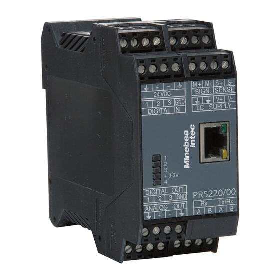
Page 12: Label On The Housing
Ethernet Transmitter Series PR 5220 Instrument Manual Label on the Housing A label with the wiring diagram is located on one side of the instrument: Housing Dimensions PR 5220/00 PR 5220/01, -/04, -/06, -/07 EN-12 Sartorius... -
Page 13: Display And Controls
* The LED for the bus activity (PR 5220/01 a. PR 5220/04) is lit as soon as there is a connection. It continues being lit, also when there is no communication, or when the physical connection is cut. 2.5.1.2 Weight Status Indicator Standstill Center zero Below zero or above max. capacity Note: The weight error status sees in Chapter 13.2. Sartorius EN-13... -
Page 14: Operation Using The Vnc Program
Ethernet Transmitter Series PR 5220 Instrument Manual 2.5.2 Operation Using the VNC Program 2.5.2.1 Operator Interface Display Function keys Alphanumeric keys Softkeys Indicator keys Navigation/menu keys EN-14 Sartorius... - Page 15 The display shows the test value without mass unit Positive value Negative value The weight value is within ±¼ d of zero The weight value is stable. Value not permissible in legal metrology (e.g., 10-fold resolution). Range 1 Range 2 Range 3 Sartorius EN-15...
- Page 16 Cursor moves to the right. Selection Cursor moves to the left. Selection Scroll up in the menu. Scroll down in the menu. Menu key Description Softkey: select function Backspace/delete Exit from current menu; continue operation on next higher level. Enter/confirm EN-16 Sartorius...
- Page 17 Softkey functions shown in gray are not available on the active menu level, or not with the active access privileges. When operating steps involving softkeys are described in this manual, the softkey labels are shown in square brackets, rather than in graphics of the softkeys. Setup Config Calib Param Sartorius EN-17...
- Page 18 W & M none Standstill time 0.50 s Standstill range 1.00 d Availability of additional settings options selectable with is indicated by preceding double arrows . Weighingpoint/WP A/Calibration Measuretime 640 ms Press to select the measuring time. EN-18 Sartorius...
-
Page 19: Overview Of Connections
PR 5220 Instrument Manual Ethernet Transmitter Series Overview of Connections Sartorius EN-19... -
Page 20: Installing The Instrument
RJ-45 socket on top of housing Remote operation of the instrument from the notebook/PC is possible; install VNC program version 3.3.7* on the notebook/PC. For setting the network address, see Chapter 4.3.3. * Sartorius guarantees the functionality only if this version is used! EN-20 Sartorius... -
Page 21: Interface
300, 600, 1200, 2400, 4800, <9600>, 19200 Bits/stop bits <8/1> or 7/1 Parity <even>, <odd>, <none> Signals RxA (R-), RxB (R+), TxA, TxB Electrical isolation Cable length max. 1000 m Cable type Shielded twisted pair (e.g. LifYCY 2x2x0.20) <...> = default settings (factory settings) Sartorius EN-21... - Page 22 [Param]: [Mode]-[single transmitter] – The following operations are possible from the connected remote display: Switch over to another weighing point Indicate current value type Set tare Reset tare Set zero Start Print EN-22 Sartorius...
- Page 23 Switch settings S1, S3 OFF: S4 is not relevant! Configuration PR 5220 -[Serial ports parameter]-[xBPI-Port]-[Builtin RS485] 3.1.2.3 Connection of a xBPI terminal Switch settings S1, S3 OFF: S4 is not relevant! Configuration PR 5220 -[Serial ports parameter]-[xBPI-Port]-[ Builtin RS485] Sartorius EN-23...
- Page 24 Installing the Instrument PR 5220 Instrument Manual 3.1.2.4 Connecting 4 Digital Load Cells Type ‚Pendeo®‘ Switch settings S1, S3 OFF: S4 is not relevant! Configuration PR 5220 -[Serial ports parameter]-[xBPI-Port]-[ Builtin RS485] EN-24 Sartorius...
-
Page 25: Analog Output
Cable length (shielded) 150 m (current output) 0/4…20mA Analog signal, current output The current is supplied directly via the terminals. 0…10V Analog signal, voltage output The voltage level corresponds to the voltage drop across the 500 ¥ (10 ppm/K) resistor. Sartorius EN-25... -
Page 26: Optocoupler Inputs
<5 mA @ 12 V DC Electrical isolation Yes; a common minus potential for the group of 3 inputs Example: contact input connection When a voltage ≥10 V DC is applied to the terminals (in the example:1-GND), input 1 is active (true). EN-26 Sartorius... -
Page 27: Optocoupler Outputs
For protection of the output circuit, relays with free-wheel diode must be provided. Example: voltage output connection When output 1 is active (true), the output voltage changes from 24/12 V DC into <3 V DC. A load resistance of 2.2/1 k¥ must be provided. Sartorius EN-27... -
Page 28: Load Cell Connection
PR 5220 Instrument Manual 3.1.6 Load Cell Connection The cable colors shown in this chapter are applicable to the Sartorius PR 62XX series load cells. Before connecting other types, carefully follow the information related to the assignment of load cell/platform cable colors. - Page 29 (symmetrical to housing GND) Sense voltage 12 V ±0,8 V (symmetrical to housing GND) Measuring voltage 0 - 12 mV @ WZ mit 1,0 mV/V 0 - 24 mV @ WZ mit 2,0 mV/V Measuring voltage 0 V ±0,5 V Sartorius EN-29...
- Page 30 Connect the instrument to PR 1626/60 as described below. For additional connections, refer to the PR 1626/60 instrument manual. The internal load cell supply voltage of PR 5220 (V+, V-) is not connected. Note: If MX8 is closed in PR 1626/60, [below 8 V DC] must be set under -[Weighingpoint]-[WP A]-[Calibration]- [Param]- [External supply]. EN-30 Sartorius...
-
Page 31: Connecting Analog Platforms (Cap
SENSE BR_NEG LC SUPPLY Connect the cable screens with the ground terminal of the instrument. If the measuring leads (+M, -M) are screened individually, these screens must also be connected to the ground terminal (see also Chapter 1.4.7). Sartorius EN-31... -
Page 32: Connecting Xbpi Platforms (Is
Connection to a RS-485 interface, see Chapter 3.1.2.2. 3.1.9 Connection of Digital Load Cells Digital load cells can be connected to the device via xBPI port and RS-485 interface. Connection to an RS-485 interface, see Chapter 3.1.2.4 . EN-32 Sartorius... -
Page 33: Profibus Interface (Pr 5220/01 Only)
Connection to the ProfiBus is using the 9-contact plug-in socket on the front panel. The transmitter is the only The transmitter is not the only Signal or last slave on the bus or last slave on the bus RxD/TxD-P CNTR-P DGND RxD/TxD-P Sartorius EN-33... -
Page 34: Devicenet Interface (Pr 5220/04 Only)
2x 2 shielded twisted pair Cable impedance 150 ¥ Bus termination 120 ¥ at the cable ends Bus load 30 mA @ 24 V DC Electrical isolation Yes, optocoupler and DC/DC converter Connecting diagram for a master with three slaves EN-34 Sartorius... -
Page 35: Profinet I/O Interface (Pr 5220/06 Only)
10 Mbit/sec and 100 Mbit/sec Autodetection (10/100, HalfDX/FullDX) Connection mode Network Protocol ProfiNet I/O Configuration XML file (‚GSDML-xxx-Sartorius-PR5220- xxx.xml’ stored on the CD in directory ‘Fieldbus’) Certificate ProfiBus Nutzerorganisation e.V. for HMS Industrial Networks AB Certificate no.: Z10006 Report: PN005-1, 12.02.2007... -
Page 36: Ethernet-Ip Interface (Pr 5220/07 Only)
Certificates/ ODVA für HMS Industrial Networks AB conformity Product code: 99 Product name: Anybus-CC EtherNet/IP SOC file name: ABCC_EIP_205_2.stc 17.04.2009 Cable Twisted pairs, screened, e.g. patch cable CAT5 Autolink (straight oder crossover) Cable impedance 150 ¥ Electrical isolation EN-36 Sartorius... -
Page 37: Commissioning
(ON) and seal the cover. To view the position of the CAL switch, select -[Show status]: Info/Status Free system RAM 4128 of 15184 kb Cal-Switch opened [opened] = opened; no write protection [closed] = closed; write protection is active Sartorius EN-37... -
Page 38: Factory Settings
(see also Chapter 4.3.3). The ‘host name’ is composed of the device name and the last 3 bytes of the MAC ID. A label with the complete MAC ID is fitted inside the door of the instrument. Hostname: PR5220-6B6A5E EN-38 Sartorius... - Page 39 The display shows: Note: At least ‘Service Pack 2’ or higher must be installed. 2. Click ‚OK’. 3. Double-click the icon for the network environment on the ‘desktop’. The display shows: 4. Click menu item ‘Tools’ -> ‘Folder Options…’. Sartorius EN-39...
- Page 40 PR 5220 Instrument Manual The display shows: 5. Click item ‘Show common tasks in folders’. 6. Click ‚OK’. 7. Click item ‘Show icons for networked UPnP devices’ in window ‘Network Tasks’ under ‘My Network Places’. The display shows: 8. Click ‚Yes’. EN-40 Sartorius...
-
Page 41: Resetting The Instrument/Activating Network'dhcp
An device set to ’on’ DHCP (default/factory setting) and connected to an IT network (company network) with a DHCP server does not require further actions except for a 2...3-minute waiting time. Subsequently, a network connection is established automatically (device <-> workstation/PC). Sartorius EN-41... - Page 42 The MAC ID or (6-digit) hardware address, e.g. 00-90-6C-6B-6A-5E is a unique number for identification of any network adaptors. A label with the complete MAC ID is fitted outside the instrument. Due to the last 3 bytes, the initialized host name is always unique. EN-42 Sartorius...
- Page 43 Always correct is the ’default’ with PR 5220-8BB499, whereby the last 3 bytes of the MAC-ID are unique. there is a limitation to 2…24 characters. Permitted are letters A…Z, a…z digits 0…9, which must not be the first or last character character "-", which must not be the first or last character Sartorius EN-43...
-
Page 44: Searching The Instrument In The Network Using 'Indicatorbrowser
If the browser window remains empty after a minimum waiting time, or if the expected device is not listed, the network ID of the local notebook/PC must be checked and changed, if necessary! Note: Only certain Sartorius devices are supported by the ’IndicatorBrowser’! EN-44 Sartorius... -
Page 45: Operation Using The Vnc Program
Webbrowser’ etc., can be used directly. The disadvantage is that an additional ‘Java’ installation is required. In addition to VNC, this includes: easy operation for back-up/restore easy operation for analysis easy operation for data of the entire device configuration, see page 47. Sartorius EN-45... -
Page 46: Operation Using Internet Browser
In earlier Windows installations, Java was provided as standard, but not activated. Example: Microsoft InternetExplorer under Windows 7 With InternetExplorer, check if the required Java (Sun) ‘applet’ is installed. If it is not installed, the link for a ‘Java’ download is suggested automatically. EN-46 Sartorius... - Page 47 Displaying the log files, see Chapter 4.11. [Screenshot] Device display for saving the display [Show error Log] Displaying and saving the error logs, see Chapter 13.5. [Backup of Earom] Saving and restoring the configuration and calibration data, see Chapter 4.12. Sartorius EN-47...
-
Page 48: Info Function
To protect the calibration data from overwriting, close the CAL switch on the back panel of the instrument. On legal-for trade instruments, the CAL switch must be sealed in the closed (write-protected) position; see Chapter 4.1.1. EN-48 Sartorius... -
Page 49: Setup Menu
<20> mA = 20 mA, linear = goes above 20 mA up to the limit - Weight at 0/4 mA Weight value for 0/4 mA output - Weight at 20 mA Weight value for 20 mA output Sartorius EN-49... - Page 50 - View(when - View(when CAL switch closed) - Max (Display only) - Scale interval (Display only) - Deadload at (Display only) - Max at (Display only) - Calibrated at (Display only) - Sensitivity (µV/d) (Display only) - Param Items as for Param. (display only) EN-50 Sartorius...
- Page 51 Momme [mom], Karat [k], Tola [tol], Baht [bat], Mesghal [m], Tonne [t] - Display accuracy 1 all digits, reduced when moved, one level lower, two level lower, three level - Display accuracy 2 lower, 1%, 0.5%, 0.2%, 0.1%, 0.05%, 0.02%, 0.01%, Multi-interval, - Display accuracy 3 increased by 10 Sartorius EN-51...
- Page 52 <0>, if >0, the serial number is checked (with verified scale) - SBN Address <0 > no bus operation. - Param - Assigned to xBPI-Port 1 - Baudrate Transmission rate: <9600>, 19200, 38400 - Bits - Parity - Stopbits <1>, 2 EN-52 Sartorius...
- Page 53 0…max. weight, transition from small to medium scale interval; only - Range limit 1 when multiple range or multi-interval has been selected. 0…max. weight, transition from medium to large scale interval; only - Range limit 2 when multiple range or multi-interval has been selected. Sartorius EN-53...
- Page 54 - Calib (when CAL-switch is closed) (display only) - Number of vessel feet (display only) - Local gravity (display only) - Max (display only) - Sccale interval (display only) - Dead load (display only) - CAL weight (display only) - Corner correction EN-54 Sartorius...
-
Page 55: Calibration Weighing Point 'Internal A
, and marked as an invalid weight with above the weight unit. After 5 s, the display returns to normal resolution. You can press the key to return to normal display immediately. Sartorius EN-55... -
Page 56: Selecting The Calibration Mode
Press [Continue] for the default settings, or [Cancel] to cancel the selection. Default settings with [New]: Weighingpoint/WP A/Calibration 3000 d 3000 kg Scale interval 3000 d 1 kg Deadload at 0.000000 Max at 1.000000 Not calibrated Sensitivity 4.000000 833.33 CalcTest EN-56 Sartorius... -
Page 57: Determining The Maximum Capacity (Max)
Weighingpoint/WP A/Calibration Max at 3000 d 3000 kg The weight unit can be changed from kg into t, g or lb by pressing After pressing confirmation of the change is displayed with: Setting Max Sartorius EN-57... - Page 58 (d) or 0.5 µV/e for legal-for-trade acc. to OIML/NSC are available. This message displays, if the maximum capacity is not an integer multiple of the scale interval. After you press [OK], the input value for the maximum capacity is canceled. EN-58 Sartorius...
-
Page 59: Determining The Scale Interval
The number of digits behind the decimal point must be determined already when entering [Max] as well. After confirmation of the change is displayed with: Set Scale interval The maximum capacity is not an integer multiple of the scale interval. Sartorius EN-59... -
Page 60: Determining The Dead Load
[by mV/V]. Weighingpoint/WP A/Calibration 3000 d 3000 kg Scale interval 3000 d 1 kg Deadload at 0.00 kg 0.000000 Max at 3000.00 kg 1.000000 Calibrated at 3000.00 kg 1.000000 Sensitivity 4.000000 833.33 by load by mV/V CalcTest EN-60 Sartorius... - Page 61 This message displays, if the Measurement signal is negative when determining the dead load with [by load]. Cause Load cells connected with wrong polarity or defective. This message displays, if dead load entered in mV/V is higher than 5 mV/V. Sartorius EN-61...
-
Page 62: Calibration With Weight (By Load)
This message displays, if the weight on the scale is less than the dead load after input of the weight value. The next step is calculation of the test value with [CalcTest] (see Chapter 4.4.11), and calibration is completed with (see Chapter 4.4.12). EN-62 Sartorius... -
Page 63: Calibration With Mv/V Value [By Mv/V]
After selecting [mV/V], the values for the Max and for the dead load (if necessary) can be entered. The next step is calculation of the test value with [CalcTest] (see Chapter 4.4.11). The calibration is completed by pressing (see Chapter 4.4.12). Sartorius EN-63... -
Page 64: Calibration With Load Cell Data ("Smart Calibration")
With [all LC same], only 1 value for the sensitivity [LC sensitivity] and the output resistance [LC resistance] must be filled in. With [each LC specific], individual values for each load cell are requested. [Calc] The mV/V value is calculated and after confirmation with [OK], the calculated mV/V value is stored in the calibration data. EN-64 Sartorius... -
Page 65: Subsequent Dead Load Correction
0.250010 2. Lin. point 1500 kg 0.500020 3. Lin. point 2250 kg 0.750040 Max at 3000.00 kg 1.000000 Change Delete by mV/V by load A linearization point can be selected with changed with [Change] and deleted with [Delete]. Sartorius EN-65... -
Page 66: Test Value Determination/Display
The confirmation is displayed as follows: Saving calibration After quitting the menu, the following message is displayed: Exit calibration After finishing the calibration, set the CAL switch to the closed position; see also Chapter 4.1.1. EN-66 Sartorius... -
Page 67: Parameter Input
The stability time must not be less than the measuring time and not greater than 32 times the measuring time. [Standstill range] The scale is stable as long as any changes in the weight value are within this range; permissible range: 0.01d to 10.00d. In 'legal-for-trade' mode select ≤1 d. Sartorius EN-67... - Page 68 [Minimum weight] Minimum weight at which a print command can still be executed. Range is 0 to 9999900 d. In 'legal-for-trade' mode min. 20 d has to be entered. [Range mode] For scale range selection, see Chapter 4.4.13.2. EN-68 Sartorius...
- Page 69 During calibration, the multiple range/multi-interval function is always switched off. Display VNC The weight display header includes the current range (R1, R2, and R3), Max, Min and d (or e with legal-for- trade instruments) (Example: multiple range scale in range 2): Sartorius EN-69...
-
Page 70: Calibrating An Xbpi Scale
Builtin RS485 Select the interface for the xBPI scale with Press [Param]. Param The menu appears. Setup/Serial ports/Slot1 RS485 Assigned to xBPI-Port Select with Baudrate 9600 bd set the following parameters with Bits Parity Stopbits 1 1, 2 EN-70 Sartorius... -
Page 71: Xbpi Scale Function
Select [Setup]. Setup Config Param Read the parameters from the xBPI scale with [Setup]. Weighingpoint/xBPI-Scale Setup Reading parameters model metrologie Ticks indicate the progress. device info settings An error message displays, unless communication with the xBPI scale is possible! Sartorius EN-71... - Page 72 Specification group 5 Specification group 6 Leave with Save changes? Save the data with [Yes]. Press [NO] for exit from the menu without data change. Weighingpoint/xBPI-Scale Setup Saving changes parameters download values Ticks indicate the progress. write nonvolatile reconfig system EN-72 Sartorius...
-
Page 73: Xbpi Scale Parameter
Select group of specification Show device info Weighingpoint/xBPI-Scale Setup Weighing parameters Open with Application settings For further procedure, see Chapter 4.5.5. Interface settings Save changes? Save the data with [Yes]. Press [NO] for exit from the menu without data change. Sartorius EN-73... -
Page 74: Xbpi Parameter Tables
- long delay - Zero range - extrem long delay - 1% of max load - Maximum capacity - 2% of max load - reduced by preload - 5% of max load - constant - 10% of max load EN-74 Sartorius... - Page 75 - 0.1% - 0.05% - 0.05% - 0.05% - 0.02% - 0.02% - 0.02% - 0.01% - 0.01% - 0.01% - Multiinterval - Multiinterval - Multiinterval - increased by 10 - increased by 10 - increased by 10 Sartorius EN-75...
- Page 76 - Parity for SBI - after 100 updates - auto when stable - Mark - Parameter change - Space - Auto print - Odd - can be changed - start/stop by ESCP - Even - cannot be changed - not stoppable EN-76 Sartorius...
-
Page 77: Xbpi Setting Dead Load
PR 5220 Instrument Manual Commissioning 4.5.6 xBPI Setting Dead Load Note: Both terms 'dead load' and 'preload' are used by Sartorius. Weighingpoint Weighingpoint A xBPI-Scale Select [xBPI-Scale] with Select [Setup]. Setup Config Param Read the parameters from the xBPI scale with [Setup]. -
Page 78: Xbpi Calibration With The User Weight
Load to small Calibration progress without weight. Cal-Target -2000 g 0.01 g The following window is displayed after applying the weight: Weighingpoint/xBPI-Scale Setup Calibration status Difference display Cal-Delta -0.3 g 1999.75 g The weight is displayed in high-resolution (10x). Select [Accept]. Accept ResError Abort EN-78 Sartorius... -
Page 79: Xbpi Calibration With Automatic Weight Detection
Adjust with user weight Adjust with auto weight Select with and enter with Following window appears: Weighingpoint/xBPI-Scale Setup Calibration status Load to small Calibration progress without weight. Cal-Target -10000.0 g The weight is displayed in high-resolution (10x). -0.02 g Sartorius EN-79... -
Page 80: Xbpi Calibration With Default Weight
The communication between instrument and platform is active. Weighingpoint/xBPI-Scale Setup Calibration Open with Configuration Select group of specification Show device info Weighingpoint/xBPI-Scale Setup Adjust with default weight Select with and enter with Adjust with intern weight Linearity Default User EN-80 Sartorius... - Page 81 Select [Accept]. Accept ResError Abort The data are saved and the instrument generates a corresponding message: Weighingpoint/xBPI-Scale Setup Calibration status complete Net=Grs 5000.0 g 5000.00 g The weight is displayed in high-resolution (10x). Accept ResError Abort Leave with Sartorius EN-81...
-
Page 82: Xbpi Calibration With Built-In Weight
Difference display Cal-Delta 0.0 g 1212.73 g Select [Accept]. Accept ResError Abort The data are saved and the instrument generates a corresponding message: Weighingpoint/xBPI-Scale Setup Calibration status complete Net=Grs -0.0 g -0.06 g Accept ResError Abort Leave with EN-82 Sartorius... -
Page 83: Calibrating Digital Load Cells Type 'Pendeo
Builtin RS485 Press to select RS-485. Press [Param]. Param The menu appears. Setup/Serial ports/Slot2 RS485 Assigned to xBPI-Port Protocol xBPI Baudrate 19200 bd Press to select the value ‚19200 bd‘. Bits Parity Stopbits 1 Press to select the value ‚1‘. Sartorius EN-83... -
Page 84: Selecting The Load Cell Type
Date & Time Operating parameter Printing parameter Fieldbus parameter Network parameter Weighingpoint Press to select Limit parameter [Weighingpoint]. Digital I/O parameter Analog output parameter Weighingpoint Weighingpoint A Pendeo Load Cells Press to select [Pendeo Load Cells] Assign Setup Config Param EN-84 Sartorius... -
Page 85: Adjustment Sequence
LC 1 Press [Search]. Search View Calib Search for connected load cells. The actual settings are reset to default. Cancel Continue Press [Cancel] to accept and display the existing values. Press [Continue] to start a new search process. Sartorius EN-85... - Page 86 Load cell load LC 4 1.828 t Press to select the desired load cell. Info Assign Press [Info] to display the load cell data. Press to return. If necessary press [Assign] to assign the load cells; see Chapter 4.6.7. EN-86 Sartorius...
-
Page 87: Assigning Load Cells
Confirm the assigning of the 1st load cell LC 4 1.828 t with The future LC no. appears at the far right of the line. Remove the weight. Repeat these steps for load cells 2–4. Press the [Accept] soft key. Info Accept Press to return. Sartorius EN-87... -
Page 88: Calibrating Load Cells
Max: the sum of the max. load cell capacity is preset (4x 50 t = 200 t). Scale interval 0.020 t Dead load CAL weight Press [New]. Param Modify When you press [New], the data is set to default first and calibration is started. EN-88 Sartorius... - Page 89 Adapt the value for Max. When entering Max, the required number of digits behind the decimal point must be taken into account. Press to switch units. [Scale interval] Select the scale interval (1, 2, 5, 10, 20 or 50). The number of intervals is calculated and fed back automatically. Sartorius EN-89...
- Page 90 Carry out a corner correction if necessary, see Chapter 4.6.9. Increased Resolution (10-fold) During calibration press to display the weight with 10-fold resolution. The resolution is reset after approx. 5 seconds. Press if you want to switch to normal resolution immediately. EN-90 Sartorius...
-
Page 91: Corner Correction
When all load cells have been loaded once, you can press [Calc] to complete the corner correction. The total weight remains unchanged. Only the effect of the individual load cells is corrected. When corner correction is completed, the marking [ok] is shown. Press to return. Sartorius EN-91... -
Page 92: Finishing/Saving The Calibration
The Confirmation is displayed with: Saving calibration After quitting the menu, the following message is displayed: Exit calibration After finishing the calibration, set the CAL switch to the closed position; see also Chapter 4.1.1. EN-92 Sartorius... -
Page 93: Parameter Input
(or by a corresponding external command), and automatic zero tracking is active. Setting range: 0.00…10000.00 d For use in Legal-for-Trade mode a value <2% of Max must be entered. Example: 60 d for 3000 e, class III. Sartorius EN-93... - Page 94 Minimum weight at which a print command can be triggered. Setting range: 0…999900 d. For use in Legal-for-Trade mode a value of at least 20 d must be set. [Range mode] For scale range selection, see Chapter 4.4.13.2. EN-94 Sartorius...
-
Page 95: Subsequent Dead Load Correction
Check the corner load, see Chapter 4.6.9.2. Local gravity 9.81379 m/s Carry out a corner correction if necessary, see 10000 d 200.000 t Chapter 4.6.9.3. Scale interval 0.020 t Dead load 7.512 t CAL weight 10 t Corner correction Sartorius EN-95... -
Page 96: Configuring General Parameters
If more than 1 instrument is connected to 1 remote display, [Mode] must be set to [multiple transmitters]. At [Device Id] the own instrument address (A, B, C ...) has to be entered, at [Next Device Id] the address of the subsequent instrument has to be entered Press to return to the menu ‚Serial ports’. EN-96 Sartorius... - Page 97 Only the baud rate and the stop bits are adjustable; the other parameters are fixed. Setup/Serial ports/Builtin RS485 Assigned to xBPI-Port Baudrate 9600 bd Press to select [Baudrate] and Bits set the baud rate with Parity Stopbits 1 1, 2 Sartorius EN-97...
-
Page 98: Operating Parameters
[disabled]: The key has no function. Closing the menu To close the menu, press . The following message is displayed: Press [Yes] to save the data. Press [No] to close the menu without changing data. EN-98 Sartorius... -
Page 99: Fieldbus Parameters
500, 250 or 125 k. DeviceNet MAC-ID address 1 ... 62. [ProfiNet I/O] Setup/Fieldbus parameter Fieldbus protocol ProfiNet I/O Use DHCP off Select on/off. IP address 192.168.1.1 Enter IP address. Subnet mask 255.255.255.0 Enter Subnet mask. Sartorius EN-99... - Page 100 192.168.1.1 Enter IP address. Subnet mask 255.255.255.0 Enter Subnet mask. Closing the menu To close the menu, press . The following message is displayed: Press [Yes] to save the data. Press [No] to close the menu without changing data. EN-100 Sartorius...
-
Page 101: Network Parameters
172.24.21.101 Access only from client machine with this address VNC-Client 172.24.21.255 Access from any client with address within range 172.24.21.1 - ..254 VNC-Client 255.255.255.255 Access from client with any address Note: When setting [IP address], [Subnet mask] and [Standard gateway], please consult with your network administrator. Sartorius EN-101... -
Page 102: Configuring Limit Values
Setup/Limit parameter Determine the limit values. Limit 1 on 890 kg Action -no action- Limit 1 off 900 kg Action -no action- Limit 2 on 300 kg Action -no action- Limit 2 off 290 kg Action -no action- EN-102 Sartorius... - Page 103 Set marker 3 clr marker 1 X64=0 Clear marker 1 clr marker 2 X65=0 Clear marker 2 clr marker 3 X66=0 Clear marker 3 Note: The limit values can be assigned to the outputs directly in the I/O parameters. Sartorius EN-103...
- Page 104 Marker bit 1 not set, after power-on the markers are set to ‘0’. marker bit 2 X65=0 Marker bit 2 not set, after power-on the markers are set to ‘0’. marker bit 3 X66=0 Marker bit 3 not set, after power-on the markers are set to ‘0’. EN-104 Sartorius...
- Page 105 Marker bit 1 set, after power-on the markers are set to ‘0’. marker bit 2 X65=1 Marker bit 2 set, after power-on the markers are set to ‘0’. marker bit 3 X66=1 Marker bit 3 set, after power-on the markers are set to ‘0’. Sartorius EN-105...
-
Page 106: Digital Outputs And Inputs
Marker bit 1 not set, after power-on the markers are set to ‘0’. marker bit 2 X65=0 Marker bit 2 not set, after power-on the markers are set to ‘0’. marker bit 3 X66=0 Marker bit 3 not set, after power-on the markers are set to ‘0’. EN-106 Sartorius... - Page 107 Marker bit 3 set, after power-on the markers are set to ‘0’. Example: ‚overload’ X34=1 Function and output are active (e. g.: if ‘overload’ is reached, a lamp is lit). X34=0 Function and output are not active (e. g.: if ‘overload’ is reached, a lamp is lit). Sartorius EN-107...
-
Page 108: Configuring Digital Inputs
X120=1 Activate a print order clr marker 1 X64=0 Clear marker 1 clr marker 2 X65=0 Clear marker 2 clr marker 3 X66=0 Clear marker 3 select gross X72=0 Save the gross weight in address D11 EN-108 Sartorius... - Page 109 Input 3 off -no action- BCD out Gross In this example: If input 1 changes from 0 to 1 [input 1 on], a taring signal is triggered only if the condition under [Condition] is met (limit 1 out = active). Sartorius EN-109...
-
Page 110: Analog Output
Set the output to 20 mA [linear] The output exceeds 20 mA up to the limitation [Weight at 0/4 mA] Weight value for 0/4 mA output [Weight at 20 mA] Weight value for 20 mA output Press to return to the previous menu. EN-110 Sartorius... -
Page 111: Adapting The Analog Output
Enter e.g. the value for 4 mA measured by the connected PLC under [Measured]. After pressing , the 2nd value (20 mA) is displayed: Info/HW-Slots/Adjust Analog Output Output 20.000 mA Measured 20.010 mA Enter e.g. the value for 20 mA measured by the connected PLC under [Measured]. Sartorius EN-111... -
Page 112: Logfiles
After selecting menu item ‘Logfiles’, several log files are listed. DIR of /var/log/ 1997 18.02.2011 10:46:21 logd.2 text/plain 10013 18.02.2011 08:05:58 logd.1 text/plain 10056 15.02.2011 19:57:52 logd.0 text/plain 3686 15.02.2011 18:24:43 messages text/plain The files contain the log lines that can be evaluated, if necessary. EN-112 Sartorius... -
Page 113: Saving Configuration Data [Backup Of Earom]
The configuration and calibration data of the EAROM can be saved for back-up on the PC and downloaded, if necessary. 4.12.1 Saving Configuration and Calibration Data Procedure: 1. Click on ‚Backup of Earom’ to open the menu ‘Backup-/Restore’. Following window appears: 2. Click on ‚Backup’. Sartorius EN-113... - Page 114 Commissioning PR 5220 Instrument Manual Following window appears: 3. Click on ‘Save’. Following window appears: 4. Create and open the required directory e.g. on the notebook. 5. Click button ‘Save’ to save the file in the relevant directory. EN-114 Sartorius...
-
Page 115: Loading Configuration And Calibration Data Into The Device
If the file is loaded into several devices, changing the network settings and the host name is indispensable! Procedure: 1. Click on ‚Backup of Earom’ to open the menu ‘Backup-/Restore’. Following window appears: 2. Click on ‚Durchsuchen’ (depending on Internet browser). Sartorius EN-115... - Page 116 PR 5220 Instrument Manual Following window appears: 3. Click the file that must be loaded. 4. Click on ‘Open’. The file is displayed in the window. 5. Click on ‚Restore’. The selected file is loaded into the device. EN-116 Sartorius...
-
Page 117: Bus/Modbus Protocol
2-byte values (16-bit values/word) have the Motorola notation. Consequence: MSB - LSB If the received command is correct but cannot be executed nevertheless (e.g. due to a faulty address or faulty data), reply is with an error telegram. Sartorius EN-117... -
Page 118: Modbus-Tcp/-Udp
With transmission problems, transmission can be The reply is transmitted quickly, or not at all. delayed considerably. Suitable for: Suitable for: Parameter transmission Transmission of dynamic values Result logging Visualization Non-time-critical process control Time-critical process control (requiring timeout handling) EN-118 Sartorius... -
Page 119: Functions
Bit 1 = bit 33 of SPM = above Max (maximum capacity) Bit 6 = bit 38 of SPM = weight is stable Bit 7 = bit 39 of SPM = weight is below zero or above Max Sartorius EN-119... - Page 120 If the address of one of the words to be read is out of the permissible range (0...63), an error message is sent as a reply (the address plus the number of bytes must not exceed 64). Example of function 3 for reading a gross weight (D8 = W16) of 893 kg with ModBus-TCP: Command Reply The individual bytes are shown. EN-120 Sartorius...
- Page 121 0...63 Reply Device address Function Word address Value of the number word 1 byte 1 byte 2 bytes 2 bytes If the address is out of the permissible range (0...63), an error message is sent as a reply. Sartorius EN-121...
- Page 122 8. The address plus the number of bits must not exceed 128. Reply Device address Function Address of the Number of bits number 1st bit 1 byte 1 byte 2 bytes 2 bytes Example of function 15 with ModBus-TCP: Command Reply The individual bytes are shown. EN-122 Sartorius...
-
Page 123: Error Messages
The address is out of the permissible range The data format is faulty (e.g. more data than specified in the number were written) Example of an error message, which was generated by an invalid function number with ModBus-RTU. Command Reply The individual bytes are shown. Sartorius EN-123... -
Page 124: Word Addresses
Below zero (minus sign) Zero within ¼ d Within zero setting range The weight is stable The weight is below zero or above Max Write bits: Set zero 1130 Set tare Reset tare For further bits, see Chapter 8. EN-124 Sartorius... -
Page 125: Sma Protocol
<yyyyyy> Text field of printable ASCII characters; for transporting scale information. The field has max. 25 characters. <uuu> Abbreviation of the used unit. The field is always 3 characters long; it is left-adjusted and filled up with spaces. Sartorius EN-125... -
Page 126: Sma Command Set
The scale repeats the weight and status information continuously until another command is received. <LF><s><r><n><m><f><xxxxxx.xxx><uuu><CR> For details, see page 130. Dependent on the used baud rate, the repetition rate of reply telegrams is roughly as follows: 19200 bd 100ms 9600 bd 110ms 4800 bd 170ms EN-126 Sartorius... - Page 127 100ms 9600 bd 110ms 4800 bd 170ms Requesting the Tare Weight Command: <LF>M<CR> Reply: The scale returns the tare weight and signals the 'tared' status in the <n> status character. <LF><s><r><T><m><f><xxxxxx.xxx><uuu><CR> For details, see page 130. Sartorius EN-127...
- Page 128 The scale deletes the tare weight and signals the tare reset status in the <n> status character. The scale tare is reset. <LF><s><r><G><m><f><xxxxxx.xxx><uuu><CR> For details, see page 130. Scale Diagnosis Command: <LF>D<CR> Reply: The scale starts the diagnosis and returns a diagnosis reply. <LF><r><e><c><m><CR> For details, see page 130. EN-128 Sartorius...
-
Page 129: Sma Reply Messages
In this section, the replies are described in detail. The data format of each reply has a fixed length. The communication error is the only exception from this pre-definable format. Thus the controlling computer can check each reply according to fixed rules, because each data field is in a fixed position. Sartorius EN-129... - Page 130 <LF> <_> <1> <G> <M> <_> <_ _ _ _ 7.650> <kg_> <CR> ... repeat... <LF> <_> <1> <G> <_> <_> <_ _ _ _ 7.650> <kg_> <CR> The scale repeats the weight, until another command is received. EN-130 Sartorius...
- Page 131 ‘E’ = EEPR OM error, ‘_’ = OK <c> ‘C’ = calibration error, ‘_’ = OK <m> Always: ‘_’ = OK <CR> Start of the diagnosis reply Example: without error status Command Reply <LF>D<CR> <LF> <_> <_> <_> <_> <CR> Sartorius EN-131...
- Page 132 <CR> End of reply from 'A'/'B' command Example: Command Reply <LF> A <CR> <LF>SMA:1/1.0 <CR> <LF> B <CR> <LF>MFG:Sartorius <CR> <LF> B <CR> <LF>MOD:PR 5220 <CR> <LF> B <CR> <LF>REV:01.01.9 <CR> <LF> B <CR> <LF>SN_:148388723 <CR> <LF> B <CR> <LF>END: <CR>...
- Page 133 <LF>END: <CR> Example: 5000g x 1g, 10000g x 2, 25000g x 5 multiple range / multi-interval Command Reply <LF> I <CR> <LF>SMA:2/1.0 <CR> <LF>N<CR> <LF>TYP:S <CR> <LF>N<CR> <LF>CAP:g_:5000:1:0 <CR> <LF>CAP:g_:10000:2:0 <CR> <LF>CAP:g_:25000:5:0 <CR> <LF>N<CR> <LF>CMD:HPTMCRQ <CR> <LF>N<CR> <LF>END: <CR> Sartorius EN-133...
-
Page 134: Communication Error
The interface protocol runs under the fieldbus and manages the access to a multitude of different data. Siemens Fieldbus Interface 8-Byte 8-Byte Write Window Read Window Data and Functions with PR 5220 Interface Weight data Weight status Protocol Limit values Digital inputs Digital outputs Analog output EN-134 Sartorius... - Page 135 2. Writing the value in bytes 0 to 3 3. Writing the register number in byte 5 (Write_Value_Select). 4. Waiting, until Write_Active = 1 (acknowledges data reception) 5. Writing 0 in b yte 5 (Write_Value_Select) -> Write_Active goes to 0. Sartorius EN-135...
-
Page 136: Description Of The I/O Area (Read / Write Window)
The test operating mode is finished. SetTest The test operating mode is started. Now the test value can be read out by reading out the gross weight. ResTare Tare is reset. SetTare The scale is tared. SetZero The scale is set to zero. EN-136 Sartorius... - Page 137 (gross <= max. capacity+overload AboveMax The weight value has exceeded the Max. capacity, but is still within Max + permissible overload (gross <= max. capacity+overload) AdcError A/D conversion error. (Details are given in register 1, Read_Value_Select = 1 Sartorius EN-137...
- Page 138 Setting bit Write_Active Waiting, until Write_Active was set Writing 0 in Write_Value_Select Resetting bit Write_Active Reading Bit Single bits can be read only by reading a register. The procedure is described in Chapter 0. EN-138 Sartorius...
- Page 139 In the event of an error: Setting the CmdError bit and LastError byte Resetting the CmdBusy bit Waiting, until was reset CmdBusy Checking the CmdError bit When set, reading (see page 138) LastError This is applicable to taring, zero setting etc. over the fieldbus. Sartorius EN-139...
-
Page 140: Special Hints For Devicenet And Ethernet-Ip
TYPE LSB Byte 1 MAINVERSION Byte 2 MAINVERSION Byte 2 TYPE LSB Byte 3 SUBVERSION Byte 3 TYPE MSB Consequently, the sequence on the PLC side must be changed when using the DeviceNet and EtherNet –IP field bus types. EN-140 Sartorius... -
Page 141: Fieldbus Register
The analog test is busy CalActive The instrument is / was configured. When this bit is 1, the scale parameters (Expo/Unit/Step) must be read again. Set after power On and reset after reading the max. capacity. TareActive The instrument was tared. Sartorius EN-141... - Page 142 Last error byte; see also CmdError bit, number of 'last error': 31 = no stability was reached (e.g. when taring) 33 = negative weight value when taring and ’legal-for-trade’ mode on 47 = no zero setting; weight not within zero setting range 107 = no stability with Getfixtare EN-142 Sartorius...
- Page 143 Reserved (free) Register 24 ... 29: Limit Values (Read/Write) Register 24 Limit 1 on Register 25 Limit 1 off Register 26 Limit 2 on Register 27 Limit 2 off Register 28 Limit 3 on Register 29 Limit 3 off Sartorius EN-143...
- Page 144 The bit is set as Write_Value_Select with the specified number (see page 138). Register 112 SetZero Register 113 SetTare Register 114 ResetTare Register 115 SetTest Register 116 ResetTest Register 117 ResetPwf Register 118 SetFixTare Register 119 GetFixTare Register 121 ResetError EN-144 Sartorius...
-
Page 145: Global Spm Variables
Command active BOOL Power fail signal BOOL Test mode active BOOL Calibration active BOOL Instrument is tared BOOL Read/write marker bit 1 BOOL Read/write marker bit 2 BOOL Read/write marker bit 3 BOOL Switch D11 to net weight Sartorius EN-145... - Page 146 BYTE Low byte of product code (0x10) BYTE Major version number (1.0) BYTE Minor version number (1.0) UDINT Boardnumber DINT Current gross weight DINT Current net weight DINT Current tare weight DINT Current gross/net weight selected with X72 EN-146 Sartorius...
- Page 147 Limit 3 off value (as float) R285 REAL Preset for fix tare (as float) R287 Conversion counter Note: For communication via OPC the system variables (e. g.: ST_WGT_A) are described in the operating manual PR 1792 (Chapter 4 + 5). Sartorius EN-147...
-
Page 148: Configuration Print-Out
Bits Limit 3 on Parity Action :set marker 3 X66=1 Stopbits Condition :no condition ----- Limit 3 off Action :clr marker 3 X66=0 Network settings Condition :no condition ----- ======================================= HW-address 00:90:6C:6A:49:81 Hostname PR5220-6B6A5E Use DHCP VNC-Client 255.255.255.255 EN-148 Sartorius... - Page 149 Power-On tare/zero : inactive Serial no. 12809189 Measure rate normal output User id tsg-1115 Calibration check :Calibration prompt Manufacturer id SARTORIUS External Adjustment: Accessible xBPI application parameters xBPI metrological data ====================================== ===================================== Application Tare Blocked Additional digits 1 unprec digits...
-
Page 150: Extended Functions
The IP address and the Hostname remain unaffected. 1. Click on 2. Click on The following message is displayed: Reply [Yes] for reset to the factory settings. Reply [No], if you want to keep the entered values unchanged. The following messages show the respective progress: EN-150 Sartorius... -
Page 151: Updating A New Software With 'Flashit
* Using a point-to-point connection the notebook/PC has to be set to a fixed IP address too. This IP address must be in the same number range, which was configured by the Subnetmask. Example: PR 5220: IP address 172.24.22.1 Notebook/PC: IP address 172.24.22.2 Device and notebook/PC have the Subnetmask 255.255.255.0. Sartorius EN-151... - Page 152 The device is restarted after the software has loaded. The next file can be loaded as described in steps 6–10. Note: If the device cannot start because the software has not loaded correctly, the first three LEDs blink in a pattern to prompt an update. EN-152 Sartorius...
-
Page 153: Repairs And Maintenance
Repairs and Maintenance 11 Repairs and Maintenance Repairs are subject to inspection and must be carried out at Sartorius. In case of defect or malfunction, please contact your local Sartorius dealer or service center for repair. When returning the instrument for repair, please include a precise and complete description of the problem. -
Page 154: Error Messages
No sense voltage No sense voltage Load cells not connected Sense line or supply line is interrupted. Wrong polarity or sense voltage is low. Negative input Negative input Wrong polarity of load cell signal. Wrong polarity of supply voltage. EN-154 Sartorius... -
Page 155: Weight Error Status
Switch the device off and on again. Wrong configuration The number of load cells does not correspond to the load cell configuration settings. Wrong serial number ‘Serial number’ does not correspond to the number set in the device. Sartorius EN-155... -
Page 156: Error Messages Of The Calibration
(d) or 0.5 µV/e for legal-for-trade acc. to OIML/NSC are available. The maximum capacity is not an integer multiple of the scale interval. Weight units do not match, e.g. subsequent change of [Max] from kg to EN-156 Sartorius... - Page 157 Adapt the filter setting; reduce the resolution. • Adapt the stability conditions. The weight on the scale is less than the dead load after input of the weight value. The maximum capacity is not an integer multiple of the scale interval. Sartorius EN-157...
-
Page 158: Show Error Log
RESET RCM:Power-On Reset [Save website], fill in the required file name and RESET RCM:Power-On Reset select the ‘txt’ file type. RESET RCM:Power-On Reset • Click [Save]. RESET RCM:Power-On Reset RESET RCM:Software Reset RESET RCM:Software Reset RESET RCM:Software Reset EN-158 Sartorius... -
Page 159: Specifications
This software, developed by third parties, is protected by copyright and is supplied free of charge. The license terms and conditions of Free Software Foundation, Inc in English are enclosed in the delivery of the instrument. The source text written under the above conditions is contained on the CD-ROM delivered with the instrument. Sartorius EN-159... -
Page 160: General Data
2 kV Peak voltages (surge) 1.2/50 µs EN 61000-4-5 1/2 kV Conducted disturbances by radio frequency (0.15…80 MHz) EN 61000-4-6 10 V 14.3.3 RF Interference Suppression Electromagnetic emission In acc. with EN 61326, limit value class A, industrial area EN-160 Sartorius... -
Page 161: Weighing Electronics
7.5 million counts at 3mV/V, not legal for trade Input voltage (input signal + dead load) 0 ... max. 36 mV DC, symmetrical to 0 Dead load range 36 mV DC (max. input signal); input/ calibration via software Sartorius EN-161... -
Page 162: Mechanical Data
0.35 kg 14.6 Use in Legal-for-Trade Mode The Guide to Verification and further documents can be found on the Internet at www.sartorius-mechatronics.com 14.6.1 Documentation for Verification on the Enclosed CD The enclosed CD has a directory containing the following PDF documents (in preparation):... -
Page 163: Index
EtherNet-IP Interface .............. 36 CAP series ..................31 External Load Cell Supply ............30 Cleaning ..................153 Commissioning ................37 Communication via OPC ............145 Configuration and calibration ..........38 Configuring General Parameters .......... 96 Connecting the Device to the Network ......39 Sartorius EN-163... - Page 164 PR 5110 ..................22 Loading Configuration Data ..........116 PR 5220/01 .................. 33 Logfiles ..................112 PR 5220/04 .................. 34 PR 5220/06 .................. 35 PR 5220/07 .................. 36 ProfiBus Interface ..............33 Profibus-DP ................. 99 ProfiNet I/O Interface .............. 35 EN-164 Sartorius...
- Page 165 Test certificate ................162 xBPI Setup for serial interface ..........83 xBPI Set-up for Serial Port ............ 70 xBPI terminal over RS-485 ............ 23 Zero setting ................. 98 Zeroset range Pendeo load cells ..............93 Zero-setting range, utilized ........... 65 Sartorius EN-165...
-
Page 166: Appendix
Appendix PR 5220 Instrument Manual 16 Appendix 16.1 Pin Assignment for Interface RS-485 PR 5110: PR 1627/PR 1628 with interface card PR 1604: Pin assignment female Pin assignment male EN-166 Sartorius... -
Page 167: Network Settings Under Windows Xp
4. Select ‘Internet Protocol (TCP/IP)’. 5. Click [Properties]. The following window appears: 6. Get the IP address automatically (DHCP), select it, or enter the relevant IP address. 7. Enter the corresponding subnet mask. 8. Click [OK] to save the entries. Sartorius EN-167... -
Page 168: Network Settings Under Windows 7
Appendix PR 5220 Instrument Manual 16.3 Network Settings under Windows 7 1. Select [Start]-[Control Panel]-[Network and Internet]-[Network and Sharing Center]. The following window appears: 2. Select ‘LAN connection’. The following window appears: 3. Click [Properties]. EN-168 Sartorius... - Page 169 4. Click ‘Internet Protocol (TCP/IP)’. 5. Click [Properties]. The following window appears: 6. Get the IP address automatically (DHCP), select it, or enter the relevant IP address. 7. Enter the corresponding subnet mask. 8. Click [OK] to save the entries. Sartorius EN-169...
- Page 172 Sartorius Mechatronics T&H GmbH Meiendorfer Straße 205 22145 Hamburg, Germany Tel +49.40.67960.303 Fax: +49.40.67960.383 www.sartorius.com © Sartorius Mechatronics T&H GmbH All rights are strictly reserved Printed in Germany...
Need help?
Do you have a question about the PR 5220 Series and is the answer not in the manual?
Questions and answers