Table of Contents
Advertisement
Quick Links
Advertisement
Table of Contents

Subscribe to Our Youtube Channel
Related Manuals for Mikasa MTX-85DY


Summary of Contents for Mikasa MTX-85DY
- Page 1 TAMPING RAMMER MTX-85DY INSTRUCTION MANUAL We thank you for selecting Mikasa Tamping Rammer. For your safe and proper operation,please read this manual and be always sure to keep it ready for reference. 302-06401 http://www.mikasas.com *302-06401*...
- Page 2 Table of contents INTRODUCTION ..................APPLICATION, STRUCTURE AND POWER TRANSMISSION ....WARNING SIGNS ..................CAUTIONS FOR SAFETY................ General Cautions Precautions When Adding Fuel Precautions About Where To Use The Machine Precautions Before Starting Work Precautions While Lifting Transportation And Storage Precautions Maintenance Precautions Label Position Label List...
- Page 3 For inquiries about repair parts, parts lists, service manuals, and repair of the machine, please contact the shop ● where you purchased it, or the Mikasa Website. In addition, parts lists are available on the MIKASA website at: http://www.mikasas.com/english/ The illustrations in this manual might slightly differ in part from the machine you actually purchased due to design changes.
-
Page 4: Warning Signs
3.WARNING SIGNS The triangle shaped marks used in this manual and on the decals stuck on the machine indicate common hazards. Be sure to read and observe the cautions described. Warning labels indicating hazards to humans and to equipment. ! Denotes an extreme hazard. - Page 5 4.2 Precautions When Adding Fuel DANGER ! When adding fuel. ■ Be sure to work in a well ventilated location. Be sure to work in a clear and flat location without any combustibles nearby. Be sure to stop the engine and wait until it has cooled down. Do not use any flames (smoking and etc.) while adding fuel.
- Page 6 Tie down the rammer with cable (wire or rope) so that it cannot move or fall over. ■ When lifting the rammer with the handle, be careful not to pinch your fingers between the handle and main body. ■ When transporting the rammer, use MC-1A of Mikasa Carry or similar product.
- Page 7 4.7 Maintenance Precautions WARNING ! ■ Ensure safety for maintenance. It needs appropriate maintenance for keeping the machine performance. Keep the machine in good condition with attention to the machine’s condition always. CAUTION ! ■ Be sure to stop the engine before maintenance of the machine. ■...
-
Page 8: Left Side View
FRONT VIEW LEFT SIDE VIEW TOP VIEW cleaner 4.9 Label List LABEL PART No. PART NAME Q’ TY REMARK 9202-21980 PLATE, SERIAL NO./MTX-85DY NPA-2198 9202-10870 DECAL,CAUTION/CONBI PL4 NPA-1087 9202-10100 DECAL,EC NOISE REQ.LWA108 NPA-1010 DECAL,LEVER OPERATION 9202-11690 NPA-1169 9209-00100 DEAL,CAUTION ICONS / MT... - Page 9 4.10 Descriptions Of The Symbols On The Warning Decals Part code No.9209-00100 DECAL, SET /MT /EXP, EU ① ② NPA-1470 ⑧ ⑨ ③ ④ ⑤ NO USE ⑩ NPA-1471 ⑦ ⑥ NPA-1474 ⑪ NPA-1472 NO USE NPA-1473 Part code No.9202-10870 DECAL, COUTION/CONBI PL4 ⑧...
-
Page 10: Specifications
5.SPECIFICATIONS 5.1 Body Model MTX-85DY Dimensions Overall height 1063 Overall width Overall length Plate Size Length Width Fuel Tank Capacity Main Body Oil API Service Categories SE or higher SAE 10W-30 Oil Capacity Number of Blow Hz/v.p.m 10.9~11.6/656~698 Impact Force kN/kgf 15.7/1,600... - Page 11 6.APPEARANCE 6.1 Appearance Dimensions ※ ...
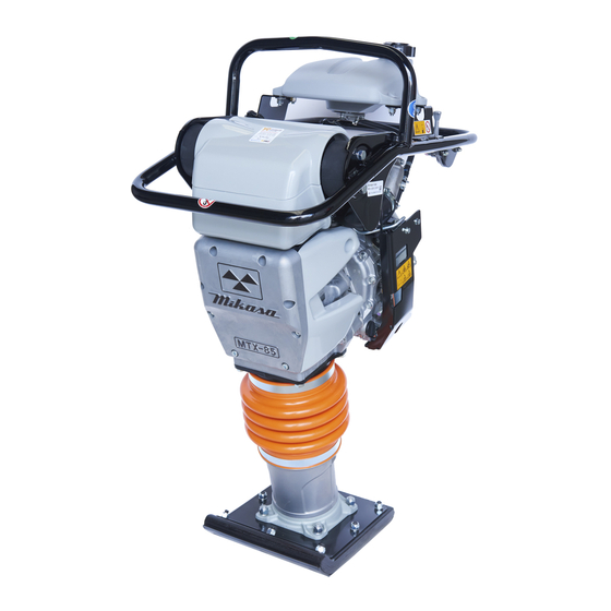
- Page 12 6.2 Control Unit Positions And Names ONE POINT LIFTING HOOK AIR CLERNER COVER HANDLE ASSY BELLOWS FOOT ASSY FUEL TANK ASSY FUEL TANK MUFFLER ENGINE CAP ASSY ASSY ASSY THROTTLE LEVER ASSY OIL INLET RECOIL PLUG STARTER OIL GAUGE FOOT PLATE DRAIN PLUG...
-
Page 13: Inspection Before Operation
7.INSPECTION BEFORE OPERATION WARNING ! Check the machine while the engine is stopped. You may be caught in a rotating ● part and be seriously injured. Check the machine after it has cooled down. Since the muffler is very hot, you may ●... -
Page 14: Operation
8.OPERATION 8.1 Starting Move the throttle lever to idle position. (Fig.4) Slowly return the recoil starter handle to the original position. After starting engine, warm up it for about five minutes by idling speed and check for fuel Idling position leakage or abnormal sounds in the meantime. Stop position CAUTION !... -
Page 15: Stopping The Machine
9.STOPPING THE MACHINE Move the throttle lever quickly from the operation position to idling position. Idling position Run the engine at idling speed for five minutes for cool down for maximum engine life. Stop position Move the throttle lever quickly from the idling position to stop position. -
Page 16: Periodic Checks And Adjustments
12.PERIODIC CHECKS AND ADJUSTMENTS Check the machine while the engine is stopped. You may be caught in a WARNING ● ! rotating part and be seriously injured. Check the machine after it has cooled down. Since the muffler is very hot, you may be ●... - Page 17 ● Change the main body oil. Remove the drain plug on the foot plate (Fig. 11) and drain the oil. Refill with approximately 820 cc of engine oil of API service categories SE or higher, SAE 10W-30. The oil level should be the halfway point of the oil gauge.
-
Page 18: Trauble Shooting
Replace it every 1000 hours of operation. Please refer to the engine operation manual for details of cleaning the oil filter of engine. Checking Fuel line Check the fuel line for damage or looseness. Replace it every 2 years, even if it does not show any abnormality. - Page 20 MIKASA SANGYO CO., LTD. 1-4-3,Kanda-Sarugakucho,Chiyoda-ku,Tokyo,101-0064,Japan PRINTED IN JAPAN...
Need help?
Do you have a question about the MTX-85DY and is the answer not in the manual?
Questions and answers