Table of Contents
Advertisement
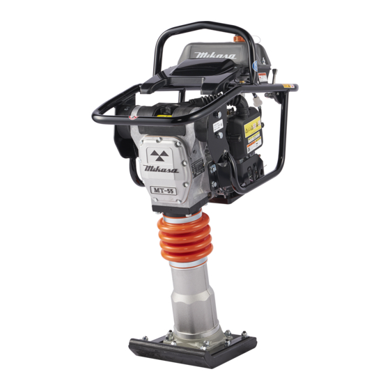
TAMPING RAMMER
MT-55
MT-65H
MT-72FW
MT-84F
INSTRUCTION MANUAL
Contents of "Declaration of Conformity"
Please refer the
EC DECLARATION OF CONFORMITY
in this manual as well.
/
55L
/
72FWA
We thank you for selecting Mikasa
Tamping Rammer.
For your safe and proper opera-
tion, please read this manual and
be always sure to keep it ready for
reference.
EN
Original
Advertisement
Table of Contents


Need help?
Do you have a question about the MT-55 and is the answer not in the manual?
Questions and answers