
Related Manuals for BEKA BA354D


Summary of Contents for BEKA BA354D
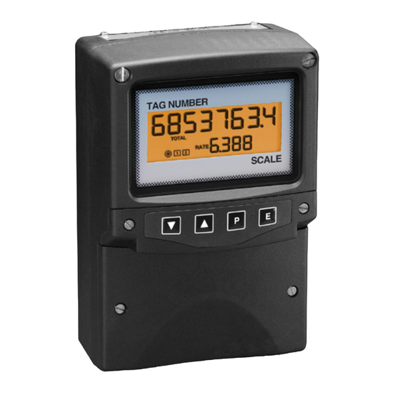
- Page 1 BA354D Intrinsically safe 4/20mA loop-powered field mounting rate totaliser issue 5 Issue: September 2008...
-
Page 2: Table Of Contents
6.13 Total scale factor 6.14 Percentage clip-off 6.15 Local reset of total display 6.16 Security code 6.17 Over and under-range The BA354D is CE marked to show compliance with the European Explosive Atmospheres Directive 94/9/EC and the European EMC Directive 2004/108/EC... -
Page 3: Description
(GRP) enclosure with an armoured glass window, push-button switches which are located behind the the BA354D is surface mounting, or may be pipe instrument control cover, or as an option on the mounted using one of the accessory kits. A stem outside of the instrument cover. -
Page 4: Displays
While this button is pushed the rate 3.1 ATEX certificate display will show the input current in The BA354D has been issued with an EC-Type mA, or as a percentage of the Examination Certificate by Notified Body ITS instrument span depending upon how... -
Page 5: Reset Terminals
3.3 Reset terminals Zone 2 explosive gas air mixture not The BA354D total display may be reset to zero by likely to occur, and if it does will connecting the reset terminals RS1 and RS2 only exist for a short time. -
Page 6: System Design For Hazardous Areas
2. The loop must be able to tolerate the additional 1.1V required to operate the indicator. Fig 2 illustrates an application in which a BA354D indicator is connected in series with a 2-wire flow transmitter protected by a Zener barrier. -
Page 7: Resetting The Total Display To Zero
4.3 Resetting the total display to zero The BA354D may be programmed to reset the total display to zero when the Up and Down buttons are pushed simultaneously for 2 seconds, or an external switch located in the safe or the hazardous area may be used. -
Page 8: Installation
Fig 5. 5.1 Location e. Replace the instrument terminal cover and The BA354D rate totaliser is housed in a robust evenly tighten the two 'A' screws. IP66 glass reinforced polyester (GRP) enclosure incorporating an armoured glass window and stainless steel fittings. - Page 9 Fig 5 Dimensions and terminal connections...
-
Page 10: Programming And Calibration
6.1 Calibration structure Fig 6 shows the BA354D calibration structure. The 4/20mA input current, which in flow applications represents flow rate, is displayed on the five digit rate display. -
Page 11: Accessing Programme Functions
For example, if a BA354D is displaying rate in litres per minute, setting 'SCALE-t' to 4.5461 produces a total display in UK gallons. Alternatively, setting 'SCALE-t' to 4546.1 will produce a total display in thousands of UK gallons. The total is calculated and the display updated twice per second, which defines the resolution of the total flow display. -
Page 14: Summary Of Programmable Functions
6.3 Summary of programmable functions Display Description of function This section summarises all of the programmable functions. When read with Figs 7A and 7B it 'Cond' Indicator conditioning provides a quick aid for calibrating the instrument. This is a protected sub-menu which If more detail is required, each section contains a contains the calibration routine for the reference to a full description of the function. - Page 15 Defines the arithmetic relationship 4/20mA output. The root extractor linearises the between the rate and total displays. flow signal and enables the BA354D to display rate May be adjusted between 0.0001 and total in linear units. and 65535...
-
Page 16: Conditioning Sub-Menu
between the two displays. When both decimal This function may also be used to calibrate a points have been correctly positioned press E to complete loop including the flow meter. return to the main menu. If the application requires flow rate to be the 6.8 Calibration of rate display using internal primary display i.e. -
Page 17: Calibration Of Internal References
This parameter defines the function of the P push- The grand total is a separate sixteen digit counter button when the BA354D is in the operating mode. which duplicates the total display but is not zeroed Either the input current in milliamps or the input as when the total display is reset to zero. -
Page 18: Percentage Clip-Off
LOC. rSET This function enables the operator to reset the Alternatively if the total display is required in BA354D total display to zero by operating the Up thousand of UK gallons and Down push-buttons simultaneously. check the status of the local reset function select... -
Page 19: Over And Under-Range
6.16 Security code: COdE To gain access to the security code link, remove The calibration and conditioning of the instrument the instrument control cover by undoing the two 'C' may be protected by a four digit security code screws - see Fig 4. If the instrument is fitted with which must be entered before access to the external push-buttons the connecting ribbon cable programme menu is granted. -
Page 20: Calibration Examples
20mA at a flow of 1100 litres / minute. or Down buttons select '50'. Finally, BA354D is required to display flow in litres per press E twice to return to the 'Cond' minute and total flow in cubic metres with a prompt in the main menu. - Page 21 Finally press E to return to the 'd.P. SCALE-t Units of rate display Units of total display prompt in the main menu. There are 1,000 litres in a cubic metre thus: Step 8 Calibrate the rate display Scroll through the main menu until litres 'CAL' is displayed.
-
Page 22: Using The Internal References
Calibration example Using the internal references In this example the internal references within the BA354D are used to calibrate the rate display. Except for steps 1, 2 and 8 the procedure is identical to that in the previous example in section... -
Page 23: Maintenance
BA354D which fails. mode override position. The exchange may be made without disconnecting See Fig 8 power, the 4/20mA loop will continue to function but the rate totaliser voltage drop will increase from 1 to 4V when the display assembly is removed. -
Page 24: Routine Maintenance
8.5 Guarantee Instruments which fail within the guarantee period should be returned to BEKA associates or our local agent. It is helpful if a brief description of the fault symptoms is provided. 8.6 Customer comments... -
Page 25: Accessories
BEKA associates The BA354D can also be supplied with a blank or custom engraved stainless steel plate secured to Fig 9 Rate alarm outputs the instrument terminal cover by tamperproof screws. -
Page 26: Intrinsic Safety
0.85W 9.2.3 Programming and adjustment No system certificate has been issued for the When a BA354D is supplied with alarms the main BA354D alarm outputs, as the system certificate programme menu is extended as shown in Fig 12. for the circuit to which the alarms are connected The two alarm functions appear between the 'C--P' remains valid. -
Page 27: Alarm Enable
Summary of programmable alarm functions 9.2.4 Alarm enable: EnbL This function allows the alarm to be enabled or Display Description of function disabled without altering any of the alarm parameters. To check or change the function 'EnbL' Alarm enable select 'EnbL' from the alarm menu and press P Enables or disables the alarm function which will reveal the current setting. - Page 28 A BA354D calibrated to display a flow of 0 to 5000, with a high alarm set at 4000 and hysteresis To check the alarm output status select 'no.nc'...
-
Page 29: Alarm Silence Time
9.2.10 Alarm delay: dELA This function enables activation of the alarm output This direct access menu is enabled and a separate to be delayed for a fixed time following the alarm security code entered from the 'AcSP' function in condition occurring. -
Page 30: Display Backlight
9.3 Display backlight BA354D supplied with backlighting to improve display contrast when the instrument is installed in a poorly illuminated area. The backlight is segregated from the measuring circuit and has been certified as a separate intrinsically safe circuit, but it does not comply with the requirements for simple apparatus. -
Page 31: External Push-Buttons
40 and 80mm. 9.6 Stem mounting kit The BA395 stem mounting kit comprises a short length of stainless steel conduit with a male M20 x 1.5 thread at both ends. Allows the BA354D to be mounted directly onto a flow transmitter. -
Page 32: Index
INDEX Subject Section Subject Section AC rejection ‘FrE’ 6.9.1 ‘LOC.rSEt’ 6.15 ‘AcSP’ 9.2.3; 9.2.12 Location Alarms optional access ‘AcSP’ 9.2.3; 9.2.12 Maintenance contacts ‘no.nc’ 9.2.3; 9.2.8 routine delay time ‘dELA’ 9.2.3; 9.2.10 Mounting kits enable ‘EnbL’ 9.2.3; 9.2.4 pipe function ‘HI.LO’ 9.2.3;... -
Page 33: Atex Dust Certification
Non European information may also be shown. A1.1 Zones and Maximum Surface Temperature The BA354D has been ATEX certified as Group II, Category 1 GD apparatus Tamb = -20 to 60 with a Maximum Surface Temperature of 80 When installed as specified by EN 61241-14 ‘Selection,...
Need help?
Do you have a question about the BA354D and is the answer not in the manual?
Questions and answers