
Related Manuals for WolfPack HDTV1000TR


Summary of Contents for WolfPack HDTV1000TR
- Page 1 User Manual HDTV1000TR PoE IP Matrix Extender with WEB GUI Control Version: V2020.001...
- Page 2 1. Introduction It’s a IP video matrix is based on TCP/IP LAN technology to process and distribute HD video signal. Better than traditional video matrix system, use distributed system architecture and embed long distance transmission function inside, which advance largely reduce infrastructure invest and installation cost.
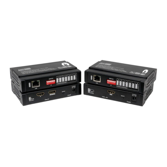
- Page 3 Descripti Output HDMI video output 12V DC Power input POWER DC 12V Input (Output 12V DC when POE working) Reset Button Long press to reset device POWER Indication Light Light on when power on Light on when receive video data from sender INPUT Indication Light Light off when no video data received...
-
Page 4: Operation Diagram
Light on when HDMI input valid INPUT Indication Light Light off when HDMI input none or invalid Back Panel Descripti Input / Output FE LAN port SWITCH Input dip switch IP Address setting IGMP Ethernet Switch Recommend using the IGMP featured ethernet switch as back-haul network to support large size matrix video distribution. - Page 5 Sender Configuration Sender should be set IP address by DIP before working. The default IP address is 192.168.1.XXX. XXX is the DIP setting value ID + 200. DIP setting value ID defined as figure below: From left to right, value of the first dip switch is 64 at the upper position, 0 at the bottom position.
-
Page 6: Device Management
Receiver Configuration Receiver should be set IP address by DIP before working. The default IP address is 192.168.1.XXX. XXX is the DIP setting value ID. DIP setting value ID defined as figure below: From left to right, value of the first dip switch is 64at the upper position, 0 at the bottom position. - Page 7 WEB GUI Management Users can use universal web browser IE, Firefox, Chrome, Safari etc. to visit device management web page. The web browser can run in PC, Pad, Phone with Windows, MacOS, Linux, ios, Android operating systems. * Notice: For different OS, device or web browser, the web page appearance could be slightly different.
- Page 8 software, etc. System Settings Click Reboot button to reboot device. Click Reset button, device will remove current settings and reset system default settings. Network Settings Network settings page shows Ethernet network setting of current device. Status Display Sender device status display page shows current video input format and audio format information.
- Page 9 6 . Matrix WEB GUI Control Switch After type the configuration and wire connection, now users are ready to do login on the browser and start the switching, the matrix switch control WEB GUI is showing as below: Receiver devices panel on left, configure receiver’s device name, video source device. The display device button aligned in the sequence of IP address.
- Page 10 Video Switch Click display device control button on left panel Video source listed on right panel Select the video source to switch Scenario Mode Switch Click Mode button on right panel Pop menu selection:“APPLY” “SAVE MODE” “CANCEL” APPLY: execute switching based on the stored connect map in this mode. SAVE MODE: store current running devices connection map in this mode and remove previous record.
- Page 11 Device and Mode name setting Click “RENAME” button on bottom panel Menu pop to choose device type or mode CHANGE TV NAME: change receiver device name. CHANGE SOURCE NAME: change sender device name. CHANGE MODE NAME: change mode name. Type in new name on right panel and click OK to sav...
-
Page 12: After-Sales
* Notice: Name string should use english characters and digits 7. After-Sales 7.1 Warranty Information The Company warrants that the process and materials of the product are not defective under normal use and service for 2 (2) years following the date of purchase from the Company or its authorized distributors. -
Page 13: Version Information
7.2 Warranty limitations and exceptions Except above limited warranty, if the product is damaged by over usage, incorrectly use, ignore, accident, unusual physical pressure or voltage, unauthorized modification, alteration or services rendered by someone other than the Company or its authorized agent, the company will not have to bear additional obligations. Except using the product properly in the proper application or normal usage 8.
Need help?
Do you have a question about the HDTV1000TR and is the answer not in the manual?
Questions and answers