Table of Contents
Advertisement
Available languages
Available languages
Quick Links
Betriebsanleitung
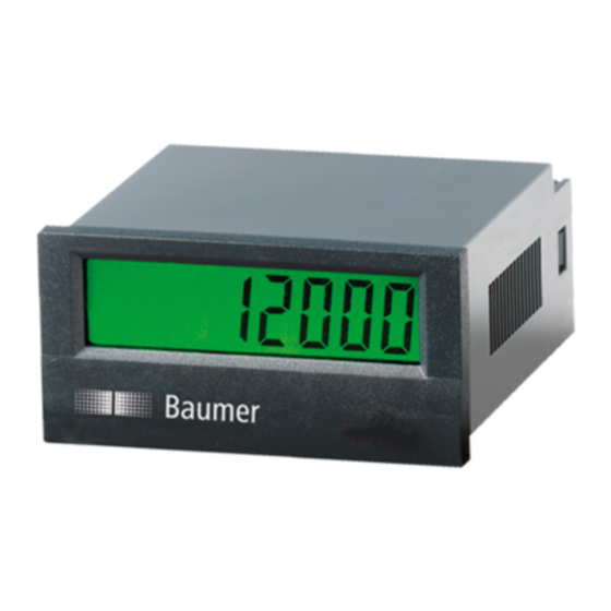
Frequenzanzeige/Tachometer
ISI36
Operating instructions
Frequency meter/Tachometer
ISI36
Instructions d'utilisation
Indicateur de tréquence/tachymétre
ISI36
Baumer IVO GmbH & Co. KG
Dauchinger Strasse 58 – 62 · DE-78056 Villingen-Schwenningen
Phone +49 (0)7720 942-0 · Fax +49 (0)7720 942-900
info.de@baumerivo.com · www.baumer.com
Sensor Solutions
Motion Control
Vision Technologies
Process Instrumentation
04/10 · 171.55.258/4
Advertisement
Table of Contents

Subscribe to Our Youtube Channel
Related Manuals for Baumer isiLine 36


Summary of Contents for Baumer isiLine 36
- Page 1 Operating instructions Frequency meter/Tachometer ISI36 Instructions d’utilisation Indicateur de tréquence/tachymétre ISI36 Baumer IVO GmbH & Co. KG 04/10 · 171.55.258/4 Dauchinger Strasse 58 – 62 · DE-78056 Villingen-Schwenningen Phone +49 (0)7720 942-0 · Fax +49 (0)7720 942-900 info.de@baumerivo.com · www.baumer.com...
- Page 2 Betriebsanleitung 1.4 Schalttafeleinbau Montieren Sie das Gerät entfernt von Wärmequellen LCD-Frequenzanzeige / Tachometer und vermeiden Sie direkten Kontakt mit ätzenden isiLine 36 Flüssigkeiten, heißem Dampf oder ähnlichen. Achten Sie bei der Installation auf eine ausreichende Kühlung des Gerätes. Beschreibung Die batteriebetriebene LCD-Frequenzanzeige/ Tachometer isiLine 1.5 Montageanleitung...
-
Page 3: Allgemeine Technische Daten
ISI36 Typenübersicht Type Betriebsart Zähleingänge INP A INP B Tacho 00 ... 0,7 V DC 7 kHz 00 ... 0,7 V DC 30 Hz ISI36.011AX01 04 ... 30 V DC 12 kHz 04 ... 30 V DC Tabelle 1 Optionen: x = A: ohne Hintergrundbeleuchtung x = B: mit Hintergrundbeleuchtung Allgemeine technische Daten:... - Page 4 ISI36 Eingangsspezifikationen und Anschlussbelegung Schraubklemme Nr. 1 Nr. 2 Nr. 3 Nr. 4 Nr. 5 Nr. 6 Nr. 7 Nr. 8 Bezeichnung INP A INP B – – Hintergrund- Hintergrund- ISI36.010AX01 30 Hz ohne Funktion 0 V DC 07 kHz beleuchtung (+) beleuchtung (–) 12 kHz...
- Page 5 ISI36 Anschlussbilder: DC-Typ: DC-Typ: ISI36.011AX01 ISI36.010AX01 max. 30 V DC max. 30 V DC INP A INP A INP B INP B n.c. n.c. n.c. n.c. n.c. n.c. (-) BL (-) BL 24 V DC ±20 %, 50 mA 24 V DC ±20 %, 50 mA (+) BL (+) BL www.b umer.com...
- Page 6 – Remove the mounting clip from the device. LCD frequency meter / tachometer – Insert the device from the front into the panel cut-out, ensur- isiLine 36 ing the front-panel gasket is correctly seated. – Slide the fixing clip from the rear onto the housing, until the...
-
Page 7: Main Technical Features
ISI36 1.10 Failure possibilities and causes If, despite all, your device still does not operate, contact your local representative or call us directly for technical support. Counter does not count: - Wrong or reversed wiring of the counting input When sending your device back, please attach a short descrip- - Polarity (NPN/PNP) reversed tion of the failure, of the programming and of the connection - No ground connection between the pulse generator and the... -
Page 8: Scope Of Delivery
ISI36 Input specification and terminal assignment Screw terminal No 3 No 4 No 5 No 6 No 2 No 7 No. 8 No 1 Designation INP A INP B – – Model ISI36.010AX01 7 kHz 30 Hz – 0 V DC Backlighting(–) Backlighting (+) ISI36.011AX01... - Page 9 ISI36 Connections: DC-Type: DC-Type: ISI36.011AX01 ISI36.010AX01 max. 30 V DC max. 30 V DC INP A INP A INP B INP B n.c. n.c. n.c. n.c. n.c. n.c. (-) BL (-) BL 24 V DC ±20 %, 50 mA 24 V DC ±20 %, 50 mA (+) BL (+) BL www.b umer.com...
- Page 10 – Glisser par l’arrière le cadre de fixation sur le boîtier jusqu’à ce Description que les étriers élastiques soient comprimés et que les ergots L’afficheur de fréquence/tachymètre à affichage LCD isiLine 36 haut et bas soient encliquetés. est alimenté par batterie. Il trouve sa place dans les applications les plus variées, par exemple: indicateur de vitesse, mesure de...
- Page 11 ISI36 1.9 Mise en route – L’appareil est-il bien réglé et programmé (fonction ; fréquence de comptage max. pour les compteurs) ? 1.10 Possibilités de défauts et leurs Le compteur ne compte pas : - Entrée de comptage mal raccordée ou raccordée à l’envers - Polarité...
-
Page 12: Affectation Des Bornes
ISI36 Affectation des bornes N° 5 Borne à vis N° 1 N° 2 N° 3 N° 4 N° 6 N° 7 N° 8 INP A INP B Désignation – – Modèle ISI36.010AX01 7 kHz – Rétroéclairage (–) Rétroéclairage (+) 30 Hz 0 V DC 12 kHz ISI36.011AX01... - Page 13 ISI36 Schémas de branchement: Type DC: Type DC: ISI36.011AX01 ISI36.010AX01 max. 30 V DC max. 30 V DC INP A INP A INP B INP B n.c. n.c. n.c. n.c. n.c. n.c. (-) BL (-) BL 24 V DC ±20 %, 50 mA 24 V DC ±20 %, 50 mA (+) BL (+) BL...
- Page 14 ISI36 Abmessungen/Dimensions/Dimensions: Schalttafelausschnitt/Panel cut- out/Découpe d’encastrement : Senkung Af3, DIN 74/Countersinking Af3, DIN 74/Fraisure Af3, DIN 74 www.b umer.com...
- Page 16 Baumer IVO GmbH & Co. KG Dauchinger Strasse 58 – 62 DE-78056 Villingen-Schwenningen Phone +49 (0)7720 942-0 Fax +49 (0)7720 942-900 info.de@baumerivo.com www.baumer.com...
Need help?
Do you have a question about the isiLine 36 and is the answer not in the manual?
Questions and answers