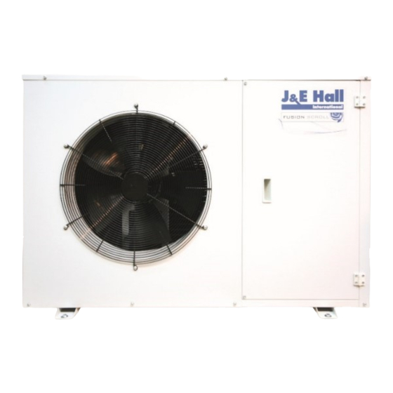
J&E Hall JEHR-0050-B1-M-1 Installation Manual
Hide thumbs
Also See for JEHR-0050-B1-M-1:
- Technical manual (36 pages) ,
- Installation manual (24 pages) ,
- Technical manual (42 pages)
Summary of Contents for J&E Hall JEHR-0050-B1-M-1
- Page 1 COMMERCIAL CONDENSING UNITS INSTALLATION MANUAL V3 FUSION & FUSION SCROLL Commercial Condensing Units Medium & Low Temperature Applications ISSUE: 01.05.2019 Contents Issue: 01.05.2019 Page 1...
-
Page 2: Table Of Contents
Contents Contents & Nomenclature Specifications Health & Safety Installation Commissioning 7-12 Wiring Diagrams 13-20 Service & Maintenance 21-22 F-Gas Information Nomenclature JEH R 0140 B 2 M 1 ① ② ③ ④ ⑤ ⑥ ⑧ ⑦ ① J & E Hall International ⑤... -
Page 3: Specifications
Type Volume Charge (W x D x H) (W x D) (m³/h) (Litres) (Litres) (Litres) (Litres) (m³/h) (inch) (inch) (mm) (mm) (kgs) dB(A) JEHR-0050-B1-M-1 1.72 1.59 1.77 1.66 1.66 1.67 AE4460Z-FZ1C 1.80 0.28 19.4 0.44 1250 JEHR-0067-B1-M-1 1.84 1.62 1.76 1.64... -
Page 4: Health & Safety
Health and Safety Installation Unit location Important Note: In order to achieve maximum cooling capacity, the installation Only qualified personnel, who are familiar with refrigeration • location for the condensing unit should be carefully selected. systems and components including all controls, should perform the installation and start-up of the system. - Page 5 Installation Tests must be conducted to ensure the amount of off-cycle Field piping • migration to the compressor does not exceed the compressor’s charge limit. Wherever possible the system should be installed to utilize a Important Note: • pump down configuration. An MOP expansion valve is recommended for all Low •...
- Page 6 Installation (C.) R407F The correction factor of refrigerant R407A is shown as below table: Amount of Sub-cooling (K) (Watts) Ta\Te 0.73 0.73 0.73 0.73 0.73 33.8 33.5 33.1 32.8 32.5 0.68 0.69 0.69 0.70 0.70 38.8 37.8 36.7 35.7 34.6 0.65 0.66 0.67...
-
Page 7: Commissioning
Installation Evacuation & Charging Mains cable type and sizing must be selected for the particular application and the electrical installation should conform to the current local standards. Important Note: Cables to the condensing unit should wherever possible • Moisture prevents proper functioning of the compressor and the be routed through the cable glands supplied on the rear refrigeration system. - Page 8 Commissioning Dual Pressure Switch Check compressor suction superheat. This should be • between 10K and 20K at normal operating conditions. Final adjustment of safety switch settings and fan speed The pressure switches fitted to condensing units with auto reset • control.
- Page 9 Commissioning XGE Fan Speed Controller (Series 2 & 3 & 4 Units) High pressure safety The fan speed controller is factory set to 19 bar for operation with R4*** series refrigerant to ensure compressor always operates The high pressure safety switch is required to stop the compressor within envelope at all declared working condition.
- Page 10 Commissioning Display/ keypad unit (LEDs and button functions) Units with microchannel condenser coils Care must be taken during charging a unit with refrigerant when a microchannel condenser coil is fitted. Because the microchannel coils hold less refrigerant than traditional fin/tube coils, it is easier to overcharge, especially if the system is commissioned during winter time when the ambient temperature is colder.
- Page 11 Commissioning Manual mode operation Warning: All alarms are disabled during manual control. We do not recommend unattended operation of system during manual control. Manual alarm reset clearing functional alarms (except hardware error) Issue: 01.05.2019 Page 11...
- Page 12 Commissioning EXD – HP1 Error/ Alarm handling Note: When multiple alarms occur, the highest priority alarm is displayed until being cleared. Then the next highest alarm is displayed until all alarms are cleared. Only then will parameters will be shown again Issue: 01.05.2019 Page 12...
-
Page 13: Wiring Diagrams
Wiring Diagrams JEHR-0050-B1-M-1 JEHR-0067-B1-M-1, JEHR-0100-B1-M-1, JEHR-0113-B1-M-1 Issue: 01.05.2019 Page 13... - Page 14 Wiring Diagrams JEHR-0115-B1-L-1, JEHR-0135-B1-L-1 JEHR-0140-B2-M-1 Issue: 01.05.2019 Page 14...
- Page 15 Wiring Diagrams JEHR-0140-B2-M-3 JEHR-0150-B2-M-1, JEHR-0175-B2-L-1, JEHR-0225-B2-L-1 Issue: 01.05.2019 Page 15...
- Page 16 Wiring Diagrams JEHR-0150-B2-M-3, JEHR-0175-B2-L-3, JEHR-0225-B2-L-3 JEHS-0200-B2-M-1, JEHS-0250-B2-M-1, JEHS-0300-B2-M-1 Issue: 01.05.2019 Page 16...
- Page 17 Wiring Diagrams JEHS-0200-B2-M-3, JEHS-0250-B2-M-3, JEHS-0300-B2-M-3, JEHS-0200-B2-L-3, JEHS-0300-B2-L-3 JEHS-0350-B3-M-1, JEHS-0400-B3-M-1 Issue: 01.05.2019 Page 17...
- Page 18 Wiring Diagrams JEHS-0350-B3-M-3, JEHS-0400-B3-M-3, JEHS-0500-B3-M-4, JEHS-0600-B3-M-3, JEHS-0680-B3-M-4, JEHS-0400-B3-L-3, JEHS-0500-B3-L-3, JEHS-0600-B3-L-3 JEHS-0800-B4-M-3, JEHS-1000-B4-M-3 Issue: 01.05.2019 Page 18...
- Page 19 Wiring Diagrams JEHS-0750-B4-L-3 JEHS-0950-B4-L-3 EVI Issue: 01.05.2019 Page 19...
- Page 20 Wiring Diagrams JEHS-1150-B4-L-3 EVI Issue: 01.05.2019 Page 20...
-
Page 21: Service & Maintenance
Service & Maintenance Important Note: Micro channel heat exchangers, because of their fin • geometry, tend to retain water more than traditional fin Warning! – Disconnect the mains electrical & tube coils. Depending on the specific design and supply before servicing or opening the unit. installation of your coil, it may be beneficial to blow or vacuum out the rinse water from your unit to speed drying and prevent pooling. - Page 22 Service & Maintenance Rotalock torque tightening values Rotolock (Suction) Rotolock (Discharge) Thread: Thread: Unit Model COMPRESSOR Tightening Torque Toghtening Torque (Nm) (Nm) AE4460Z-FZ1C JEHR-0050-B1-M-1 CAJ9480Z JEHR-0067-B1-M-1 Not Applicable CAJ9510Z JEHR-0100-B1-M-1 (Brazed Connection) CAJ9513Z JEHR-0113-B1-M-1 CAJ4517Z JEHR-0140-B2-M-1 TAJ4517Z JEHR-0140-B2-M-3 MTZ018-5VM 1"-14 UNS...
-
Page 23: F-Gas Information
F-Gas Information From 1/1/2015, F-Gas Regulation EU 517/2014 came into force replacing the old Regulation EC 842/2006. This affects system labelling, information supplied within documentation and also the way in which thresholds for frequency of leak testing refrigeration systems are calculated. Please be aware of the following: The models of equipment covered in this Technical Manual rely on fluorinated greenhouse gases for their functioning. - Page 24 J & E Hall Limited Hansard Gate West Meadows Derby, DE21 6JN England Tel: + 44 (0) 1332 253400 Fax: + 44 (0) 1332 371061 Email: helpline@jehall.co.uk www.jehall.com Issue: 01.05.2019...


Need help?
Do you have a question about the JEHR-0050-B1-M-1 and is the answer not in the manual?
Questions and answers