
Related Manuals for J&E Hall JEHSD-0600-M-3


Summary of Contents for J&E Hall JEHSD-0600-M-3
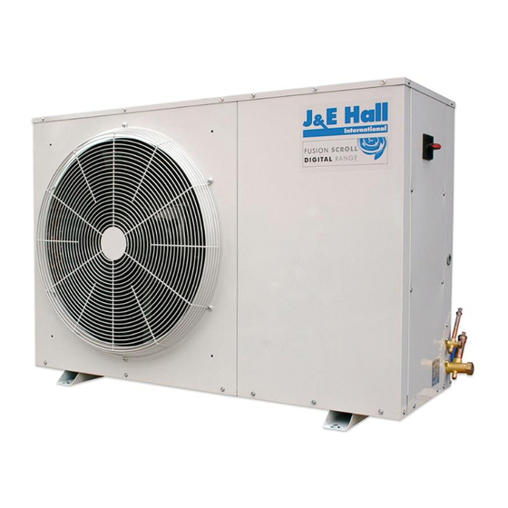
- Page 1 COMMERCIAL CONDENSING UNITS TECHNICAL MANUAL TECHNICAL MANUAL FUSION DIGITAL SCROLL Commercial Condensing Units Variable Capacity Medium Temperature Applications ISSUE: 01.05.2017...
-
Page 2: Table Of Contents
Contents Nomenclature Standard Product Configuration Specifications Health & Safety Installation 10-13 Commissioning 14-22 Control Logic 23-24 Alarm Information 25-26 Drawings 27-28 Service & Maintenance 29-30 F-Gas Information Technical Information 32-35 Certification 36-38 Issue: 01.05.2017 Page 2... -
Page 3: Nomenclature
Nomenclature JEHSD - 0600 - M - 3 3: Three Phase Application: M: Medium Temperature Nominal Capacity in Horse Power 0600: 6.0 HP D: Digital S: Scroll JEH: J & E Hall International Issue: 01.05.2017 Page 3... -
Page 4: Standard Product Configuration
Standard Product Configuration Single Digital Scroll • Copeland hermetic digital scroll compressor – ZBD (Digital) • Variable compressor capacity control • 7.6 litre vertical liquid receiver with fusible plug • Fitted liquid line drier & sight glass • Oil separator and discharge check valve •... -
Page 5: Specifications
(m³/h) (Litres) (Litres) (Litres) (Litres) (m³/h) (inch) (inch) (kgs) dB(A) JEHSD-0600-M-3 ZBD45KQE-TFD 17.1 1.89 13.5 74.0 4150 Oil Type A = Polyolester Oil - (Copeland Ultra 22 CC, Copeland Ultra 32 CC, Copeland Ultra 32-3MAF, Mobil EAL Arctic 222CC, Uniquema Emkarate RL32CF NC = Nominal Current @ condition -10°C Te / +32°C Ta MT w ith R404A refrigerant... - Page 6 4420 4780 5140 5500 5840 6240 1.64 1.83 2.00 2.18 2.38 2.61 2.81 6410 7705 9080 10650 12450 14500 16700 JEHSD-0600-M-3 6.00 4295 4620 4995 5365 5730 6075 6480 R404A 1.49 1.67 1.82 1.99 2.17 2.39 2.58 6090 7320 8610...
- Page 7 4230 4640 5070 5460 5830 6170 1.63 1.81 2.01 2.19 2.42 2.68 3.00 5945 7370 8965 10725 12800 15225 18075 JEHSD-0600-M-3 6.00 4000 4440 4865 5295 5680 6040 6360 R448A 1.49 1.67 1.85 2.03 2.26 2.53 2.85 5680 7070 8620...
- Page 8 Specifications Product Information based on the requirements of Commission Regulation EU 2015/1095 Model : JEHSD-0600-M-3 Refrigerant fluid: R404A R407A R407F R448A R449A Item Value Symbol Unit Evaporating temperature* ⁰C Annual electricity consumption 22130 19926 22051 21767 21767 kWh/a Seasonal Energy Performance Ratio SEPR 2.65...
-
Page 9: Health & Safety
Health and Safety Important Note: Only qualified personnel, who are familiar with refrigeration systems and components including all controls, should perform the installation and start-up of the system. To avoid potential injury, use care when working around coil surfaces or sharp edges of metal cabinets. All piping and electrical wiring should be installed in accordance with all applicable codes, ordinances and local by-laws. -
Page 10: Installation
Installation Unit Location • In order to achieve maximum cooling capacity, the installation location for the condensing unit should be carefully selected. • Install the condensing unit in such a way so that hot air ejected by the condensing unit cannot be drawn in again (short circuit of hot discharge air). - Page 11 Installation Field Piping Important Note: Pipe sizing should only be determined by qualified personnel. All local codes of practice must be observed in the installation of refrigerant piping. To ensure satisfactory operation and performance, the following points should be noted for field piping arrangements: •...
-
Page 12: Pressure Testing
Installation Pressure Testing The condensing units are pressure tested in the factory prior to dispatch. All units come with a holding charge of oxygen free nitrogen (OFN). Once the pipework installation is complete, it should be pressure tested prior to evacuation to test for leaks. A pressure leak test should be carried out using OFN. - Page 13 Installation Electrical Important Note: The mains electrical supply to the condensing unit must be via a suitable motor rated circuit breaker or fuse. A mains isolator is fitted to all condensing units therefore an additional isolator is not required unless site conditions or regulations dictate differently.
-
Page 14: Commissioning
Commissioning Access to Controller and LCD Display Important Note: Warning! Only Authorized personnel are allowed to access the controller and LCD display. The controller and LCD display are accessed by removing both the end service panel and front panel. Issue: 01.05.2017 Page 14... - Page 15 Commissioning Pre Startup Checks Before starting the condensing unit the following checks should be carried out as a minimum: • Check electrical supply is correct and all connections are sound. • All moving parts are free and guards fitted. • Compressor oil level satisfactory. •...
- Page 16 Commissioning The User Terminal Interface – LCD Display The user terminal can be used to perform all the operations allowed by the program, display the operating conditions of the unit at all times, and set the parameters. It can be disconnected from the main board, and in fact is not required for operation. Button Functions ALARM Displays the alarms...
- Page 17 Commissioning Controller Home Screen Following controller power-up and initialisation process (approximately 1 minute), the controller home screen will appear as follows: The low pressure and high pressure conditions of the unit are displayed. If OFF by Key is indicated in the lower box, then the unit is switched OFF on the controller.
- Page 18 Commissioning Changing Set Point & Refrigerant Selection 1. With controller Home screen displayed, Press PRG button to go Main Menu screen and select “B. Setpoint” using DOWN button. Press ENTER button. Screen B01 is displayed. 2. Using ENTER button, move the cursor from the ‘home’ position to the Compressor Setpoint and adjust value as required by using UP or DOWN buttons.
- Page 19 Commissioning Switch Unit On/Off (By Controller) 1. With controller Home screen displayed, Press PRG button to go Main Menu screen and select “A. On/Off Unit” 2. Press ENTER button. Screen A01 is displayed. 3. Press ENTER button to move cursor from home position to SWITCH OFF value. Switch Unit ON by using UP/DOWN arrows.
-
Page 20: Compressor Operation
Commissioning Compressor Operation The compressor(s) operate in accordance to the suction pressure setpoint which is programmed into the controller. There is a differential pressure setting both above and below the setpoint. This allows stable operation of the compressors without constantly switching on & off due to small variations in suction pressure. - Page 21 For operation in bypass mode, the low pressure control should be set to control the compressor (fixed speed only for twin compressor) at the required SST according to the application. If adjusted for operation in bypass mode, the low pressure control must be reset to factory setting as below before returning to Normal (controller) operation. Unit JEHSD-0600-M-3 Refrigerant R404A/R407A/R407F/R448A/R449A Application Cut Out / Cut In (bar g) 1.0 / 3.0...
-
Page 22: Commissioning
Commissioning Manual Bypass Operation In the event of failure of the main electronic controller, the unit can be run temporarily in mechanical bypass mode. By changing the position of the two manual bypass switches mounted in the cover of the controller electrical box from ‘0’ to ‘1’, the compressor will run at 100% capacity –... -
Page 23: Control Logic
Control Logic Parameters for neutral zone compressor control 1. Preset differentials for neutral zone, activation zone and deactivation zone. Neutral zone The operating principle is schematized in the above figure: Inside the neutral zone the capacity request sent by the controller is constant (except when there is a modulation device and modulation is enabled inside the neutral zone) and the value satisfies the pressure control request in those specific operating conditions. - Page 24 Control Logic Parameters for neutral zone compressor control As well as the decrease and increase differentials, 4 time parameters are preset, two for each zone, which represent the maximum and minimum time to reach the request, equal to 0% or 100%, for the decrease and increase respectively.
-
Page 25: Alarm Information
Alarm Information Alarm Settings 1. Low pressure alarm (by transducer) 2. High pressure alarm (by transducer) 3. High condensing coil temperature alarm 4. High discharge alarm for fixed scroll compressor (if applicable) Issue: 01.05.2017 Page 25... - Page 26 Alarm Information Alarm Codes Type of alarm The alarms below are in ascending order of priority. When there is any alarm, the alarm code will be displayed on the main screen and the alarm LED will be on or blinking. Code Description Reset type...
-
Page 27: Drawings
Drawings Dimensional drawing: JEHSD-0600-M-3 Issue: 01.05.2017 Page 27... - Page 28 Drawings Electrical Wiring Diagram: JEHSD-0600-M-3 Issue: 01.05.2017 Page 28...
-
Page 29: Service & Maintenance
Service & Maintenance Important Note: Warning! – Disconnect the mains electrical supply before servicing or opening the unit. The condensing units are designed to give long life operation with minimum maintenance. However, they should be routinely checked and the following service schedule is recommended under normal circumstances: The removal of the top, side and front panels ensures that all parts are accessible. - Page 30 Service & Maintenance 4. Controls • Check settings and operation of controller and transducers/sensors. • Check settings and operation of pressure switches. • Check overload setting. • Check fan speed control setting and operation. 5. Power Supply – Inspect at regular intervals. •...
-
Page 31: F-Gas Information
F-Gas Information From 1/1/2015, F-Gas Regulation EU 517/2014 came into force replacing the old Regulation EC 842/2006. This affects system labelling, information supplied within documentation and also the way in which thresholds for frequency of leak testing refrigeration systems are calculated. Please be aware of the following: •... -
Page 32: Technical Information
Technical Information SNS Pressure Switch Safety pressure switch settings: The pressure switch fitted to condensing units with auto reset for low pressure is factory preset to 1.0 bar cut-out. Do not set pressure control below this setting. 1. Micro Switch 5. - Page 33 Technical Information Medium Version Controller Please Note: The battery in the controller should be changed every three years. Issue: 01.05.2017 Page 33...
- Page 34 Technical Information Medium Version Controller Issue: 01.05.2017 Page 34...
- Page 35 Technical Information Oil Separator Technical Data Operating Medium R404A Design Pressure, DP (MPa) Design Temperature, TS ( -40 ~ 130 Maximum Allowable pressure (MPa) Weight (kg) Marking Initial Oil Connection Volume Type Part No. Charge Category Litres Litres RSPW 55877 7/8‘‘...
-
Page 36: Certification
Certification Issue: 01.05.2017 Page 36... - Page 37 Certification Issue: 01.05.2017 Page 37...
- Page 38 Certification Issue: 01.05.2017 Page 38...
- Page 39 THIS PAGE IS LEFT BLANK INTENTIONALLY Issue: 01.05.2017 Page 39...
- Page 40 J & E Hall Limited Hansard Gate West Meadows Derby, DE21 6JN England Tel: + 44 (0) 1332 253400 Fax: + 44 (0) 1332 371061 Email: helpline@jehall.co.uk www.jehall.com Issue: 01.05.2017...
Need help?
Do you have a question about the JEHSD-0600-M-3 and is the answer not in the manual?
Questions and answers