Advertisement
Quick Links
Seat Seal Kit
Seat O-ring (2)
Seat spring (2)
Backup ring (2)
Gasket (2)
Tools Required
Part
Valve body
End screw
Packing bolt
Packing bolt,
end screw
WARNING
BEFORE REMOVING A VALVE FROM THE SYSTEM FOR SERVICE, YOU MUST
•
depressurize system
•
cycle the valve
•
purge the valve.
MS-CRD-AFS
MS-CRD-AFS
R1 06-05-CP
Swagelok
®
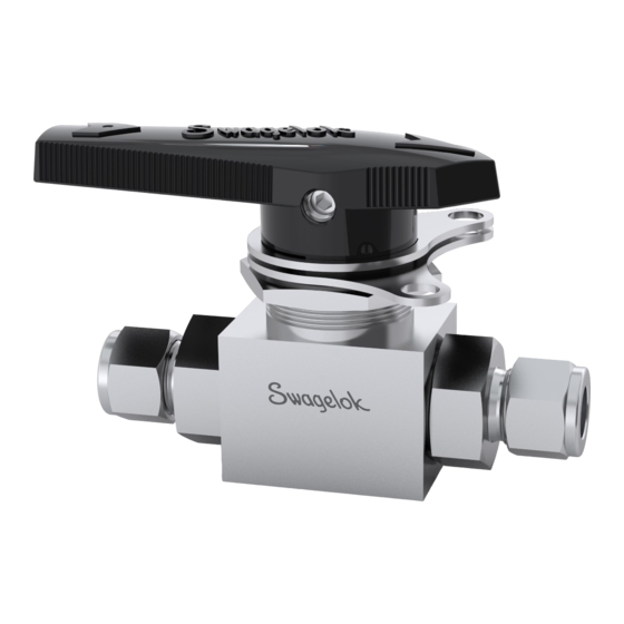
Alternative Fuel Service (AFS) Ball Valve
Seat (2)
Lubricant
Tool
Bench vise
Open-end wrench
Open-end wrench
Crow's foot
Socket
Socket
Torque wrench
Service Instructions
Stem and Seat Seal Kit
Stem guide
Stem backup
ring (2)
Stem thrust
Packing bolt
washer
gasket
Backup ring (2)
Seat O-ring (2)
Lubricant
Gasket (2)
Optional: Small nonmetallic pick
Stem O-ring
ring
Seat spring (2)
Seat (2)
Size
—
1 1/2 in.
1 3/16 in. (30 mm)
13/16 in.
600 to 700 in.·lb
(68 to 79.1 N·m)
(692 to 806 cm·kg)
Advertisement

Related Manuals for Swagelok AFS Series


Summary of Contents for Swagelok AFS Series
- Page 1 Swagelok ® Alternative Fuel Service (AFS) Ball Valve Service Instructions Seat Seal Kit Stem and Seat Seal Kit Stem guide Stem backup Seat O-ring (2) Seat (2) Seat spring (2) Stem O-ring ring (2) ring Stem thrust Packing bolt Backup ring (2)
- Page 2 Refer to the Fig. 1 while following these instructions. 10. Remove the stem guide rings, stem backup ring, Complete the maintenance on one end screw assembly stem O-ring, and stem thrust washer from stem before proceeding to the other end screw assembly. and discard.
- Page 3 Locking Bracket Kit Bottom Bottom Cut out bracket bracket Notch Bottom bracket Top bracket Tools Required Hex key Torque wrench Fig. 3 5/32 in. 80 to 110 in.·lb (9.0 to 12.4 N·m) (92 to 127 cm·kg) 4. Turn the handle upside down and place the top bracket on the base of the handle aligning the cut out in the bracket with the notch on the handle.
- Page 4 4. Thread the set screw into the handle and tighten to 80 to 110 in.·lb (9.0 to 12.4 N·m) (92 to 127 cm·kg). 5. Test the valve for proper operation. Handle Set screw Stem flat Fig. Fig. 6 Swagelok—TM Swagelok Company © 2004, 2005 Swagelok Company MS-CRD-AFS MS-CRD-AFS R1 06-05-CP...
Need help?
Do you have a question about the AFS Series and is the answer not in the manual?
Questions and answers